This thread has been locked.

If you have a related question, please click the "Ask a related question" button in the top right corner. The newly created question will be automatically linked to this question.

Help for PCB Antenna Return Loss Measurement

Other Parts Discussed in Thread: CC2511

Hi,


I am trying to measure the return loss of a PCB using TI BLE with a meandered antenna at 2450 MHz, the same antenna with the same dimensions as in the TI Application Note AN043 using a VNA.


On the PCB there is a balun (classical one with lumped elements), a matching circuit and the antenna. I am supposing that the output of the balun is 50 ohms and I am trying to measure the return loss at the input of the matching circuit and then in case the antenna is not well matched make it shorter untill achieve a good matching at 2450 MHz.

I am new on RF measurements so  I want to have your help.

From my understanding, I guess I should cut the microstrip line going from the balun to the matching circuit and solder a coaxial cable RG316/U with SMA connector at the entrance of the matching circuit. Is it right?.
Then on the Network Analyzer I should make a calibration with a calibration kit a then do a port extension indicating the length of the coaxial cable soldered on the PCB. Is it right?

Thanks,


Juan

  • As a reference look at chapter 6 in www.ti.com/lit/an/swra161b/swra161b.pdf

    Yes, cut the connection between the balun and the matching circuit.

    Yes, you need to do a calibration and then a port extension. Some VNAs are able to do automatic port extension, then you have to do this before you solder the semi rigid onto the board.

  • Thank you very much for your quick answer.

    I am following the measurement procedure you commented:

    * cut the connection between the balun and the matching circuit
    * Calibration + port extension (till have an open in the smith chart before soldering the cable)
    * solder the coaxial cable at the input of the matching circuit

    * first I replace the matching circuit elements with resistances of 0 ohm and I measure the impedance of the antenna without matching circuit.

    * I calculate the values of the pi-matching network (using Microwave Office or other matching circuit calculator) and the simulations show a good matching at 2.45 GHz

    The problem comes when I replace the null ohm resistances by the components simulated on the PCB, and repeat the measurement, the antenna is not matched around 2.45 GHz but 200 MHz lower. That's why I had some doubts about the measurement configuration. Any idea about what can be the problem please?

  • Simulations normally gives an offset compared to real measurements due to parasitic, layout effects etc etc. Spending too much time to get the simulations correct is not something I would recommend. Rather let the simulations give you an indication and let the practical measurements give you the answer. The resonance will depend on many factors like size of ground plane, distance to ground plane, objects in the near field etc etc, sometimes simply cutting the antenna length (thus moving the resonance to a higher freq) is the easiest solution.  

  • Hi,

    Taking into account the answers that you gave me, I wanted today to check my measurements by trying to measure the return loss of a TI reference design : the USB dongle CC2511 and to compare it with the measurements results presented in the application note AN043.

    First I disconnected the antenna from the radio part and I measure it with a semi-rigid cable connected to the feed point of the meandered antenna and then I measured it with the matching circuit.

    In both cases I didn´t obtain a matching in the 2,4-2,5 GHz but more or less around 2,2-2,3 GHz.

    So I deduced that maybe something is wrong with the measurement procedure I am using even if I realized well the calibration and then the port extension (Automatic length and Automatic offset). Before soldering the semi-rigid coaxial cable I checked that  I have an open in the smith chart of my network analyzer.

    Do you have any idea about what can be the fail? Maybe the semi-rigid cable? Can you tell me please some references of semi-rigid cables?

    Thank you very much for your help.

  • If you measure open with the VNA including the semi rigid your calibration + semi rigid is ok. Have you connected the shield close to the tip of the semi rigid to ground? Could you post a picture showing how you have soldered the cable onto the board you are measuring on?

  • TER said:

    If you measure open with the VNA including the semi rigid your calibration + semi rigid is ok. Have you connected the shield close to the tip of the semi rigid to ground? Could you post a picture showing how you have soldered the cable onto the board you are measuring on?

    Hi,

    I am new on RF measurements so I will explain more or less the steps I followed from my understanding, maybe I am doing something wrong.

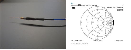
    For the VNA, I connect the test cable and I calibrate it with the calibration kit then I connect the semi-rigid cable and I make a port extension pulsing the option of automatic length and offset  that has the VNA. I check that on the smith chart I am around the open area (when I do the test like in the first image) . the test cable and the semi-rigid cable are both SMA-male so I use a SMA  female female adaptor. but I guess that it is also taken into account in the port extension.


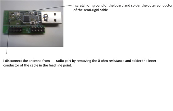
    Then on the PCB, I disconnect the antenna from the radio part by removing the 0 ohm resistance and I solder the inner part of the cable on the feed line and I scratch off the ground plane on the PCB and solder the outer part of the cable (As shown in the image)

    I measure with the usb dongle on horizontal position on a desk. What I obtain with this measurement is something like this with a resonnance at 2.17 GHz instead of in the band 2.4 - 2.5  GHz :

    I am doing something wrong on the measurement but I don't know what. I have tried many times this last days soldering the cable in different positions and I don't know if you have an idea about what can be the problem.

    Thank you very much for your help,

  • You are measuring a monopole antenna which actually is an dipole but half of it is buried in ground.
    Antenna part that is buried in ground, is depending on ground plane size and shape. When ground plane is short relative wavelength do measurement cable braid heavily act as an extension of ground plane.It is therefore not surprising that measured resonance frequency is a bit low. as your measument cable now is a part of the antenna This can be corrected by doing as in section "Measurement cable" at http://www.antune.net/calibration.html.

    As actual PCB have an USB connector, if it is inserted in something with ground plane, will that also affect total size of ground. In general, longer and wider ground will reduce resonance frequency. If a plastic cover is added for the PCB can that also affect antenna impedance and reduce resonance frequency.

  • BF, 

    The last comment is correct, the monopole antenna is very dependent on ground plane size and shape. To show this I recommend that you insert the USB stick into laptop computer and re-measure. You will find the S11 to have changed, but likely just the "nul". 

    I find the most important part when evaluating antenna is not spending too much time on where the "nul" is, is not as important as spending time on where the -6dB crossing are.

    From you graph it looks like it is pretty wide band, however still low at 1.8 - 2.6GHz or a center of 2.2GHz.

    Regards,
    /TA