This thread has been locked.

If you have a related question, please click the "Ask a related question" button in the top right corner. The newly created question will be automatically linked to this question.

Software Packet Handler using uC to test Rx

Other Parts Discussed in Thread: CC1125

Hi

  I want to create the packets using microcontroller ,as same as CC1125 hardware packet handler.

We need this to test the Receiver perfomance and error rates.


Hope you might have some routines for this. Can you share and guide me to create a minimum of

Preamble+ Sync+legnth+ payload+CRC (Which all are taken for CRC calculation?) and manchester bi-phase encoding (Is this manchester encodes only payload or full frame?)

these full packet frame, i need to shift out in IO pin of micro controller .

  • Hi

    Look at the software examples for the CC112x;


    http://www.ti.com/lit/zip/swrc253

    and the PER test:

    http://www.ti.com/lit/zip/swrc219

  • Hi

      Are you mentioning the Createpacket in the below code snippet from

    http://www.ti.com/lit/zip/swrc253 

    If that, i may asked wrongly. I dont want to use the CC1125 as Transmitter.  

    I want to create a packet in MCU and send output it as like SPI data out pin. (Not the SPI , just an example i am saying)

    // Infinite loop
        while(TRUE) {
    
            // Wait for button push
            if(bspKeyPushed(BSP_KEY_ALL)) {
    
                // Continiously sent packets until button is pressed
                do {
    
                    // Update packet counter
                    packetCounter++;
    
                    // Create a random packet with PKTLEN + 2 byte packet
                    // counter + n x random bytes
                    createPacket(txBuffer);
    
                    // Write packet to TX FIFO
                    cc112xSpiWriteTxFifo(txBuffer, sizeof(txBuffer));
    
                    // Strobe TX to send packet
                    trxSpiCmdStrobe(CC112X_STX);
    
                    // Wait for interrupt that packet has been sent.
                    // (Assumes the GPIO connected to the radioRxTxISR function is
                    // set to GPIOx_CFG = 0x06)
                    while(packetSemaphore != ISR_ACTION_REQUIRED);
    
                    // Clear semaphore flag
                    packetSemaphore = ISR_IDLE;
    
                    // Update LCD
                    updateLcd();
                } while (!bspKeyPushed(BSP_KEY_ALL));
            }
        }
    }

  • Hi

    The createPacket routine creates a packet (payload only) and the cc112xSpiWriteTxFifo writes the packet to the CC12x' TXFIFO over SPI. All these routines are done by the MCU and data is both read and written over SPI to the radio.. Preamble, sync word and CRC are automatically added by the radio before transmitting the packet.

    As I understand it this is what you are trying to do? Or am I not understanding you correctly?

  • Hi

       No.  I am not asking this.


    Without Using the Radio ( CC1125)  after your createPacket rountine, i want to add Preamble,Sync word and CRC in the MCU itself.
    That is, need to do Full packet framing inside the MCU.

    Hope i explained clearly , if not please let me know.

    Thank you

    Vijay

  • Ok

    If you do not want the CC1125 to add the preamble and sync word, you have to modify the createPacket routine to add the preamble and sync bytes before the payload. So the first bytes in the txBuffer array will contain the preamble and sync bytes that you want followed by the length byte and payload. The last two bytes in the array should then contain the CRC bytes. For the CRC you can look at DN502 CRC Implementation on how to implement the CRC routine in SW.


  • Well thank you , and i will look into CRC .

    By the way, i need some more info ,

    1. To know what is the value of  Sync bits, SYNC_CFG0.SYNC_MODE = 001. Means 11bits,  What is the real value

              of  11bits? Where to get it?

    2. I need to do Manchester Encoding also. In CC1125, Is this encoded for whole frame or only for the payload as like CRC.  Is this Bi-phase Manchester?

    3. The Timing requirement of Data shifting out for each bit of frame. What is the bit timing of CC1125 radio using ?

         Is this depends on RF Symbol Rate/ Bit Rate?

  • Hi

    1. The sync word can be programmed in the SYNC3 to SYNC0 registers. When SYNC_CFG0.SYNC_MODE is set to 11 bits its the SYNC0 register and the 3 LSB of SYNC1 that is used.
    2. The CC1125 will Manchester encode the payload including the CRC bytes. Preamble and sync word will be send in normal FSK. I'm not sure what you mean by bi-phase Manchester. The Manchester scheme for the CC1125 will be a logic 0 for low to high transition and a logic 1 for a high to low transition.
    3. This is dependent of the data rate. Please see section 8.7 in the users guide regarding Transparent and synchronous serial operation. 
  • Hi

    I Finished upto shifting out the packet (added preamble, sync,length,payload) data in an MCU GPIO.

    Now my issue is Symbol rate(i am not sure this is bit timing or symbol rate) of the Data out from MCU GPIO

    Martin B said:
    • This is dependent of the data rate. Please see section 8.7 in the users guide regarding Transparent and synchronous serial operation. 


    I read this section 8.7 , i could not find anything about the symbol rate except the below line

               In transparent serial mode the symbol rate programming does not affect operation.

    Can you explain me what timing i have to use ?


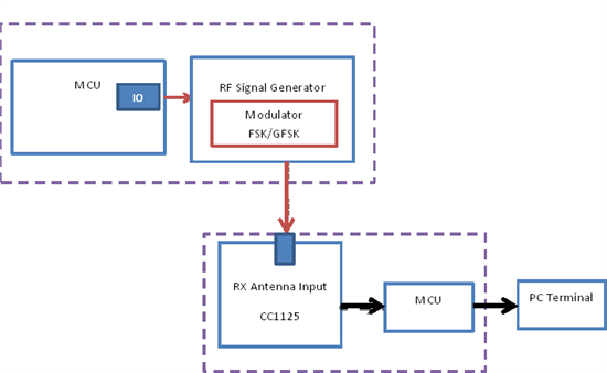
    Reason of asking these is , to test the Receiver performance as the below test setup Image.

  • Hi

    Looking at your test setup I would strongly suggest to use the packet handling feature of the CC1125, either by normal FIFO mode or synchronous serial mode. For both these modes the symbol rate used is the one you program in the SYMBOL_RATEx registers.

    For FIFO mode you do not need to think about any timing as the packet will be placed in the RXFIFO and the MCU can read it out through the SPI interface. For synchronous serial mode you will have a SERIAL_CLOCK signal on the GPIO that is coherent with the symbol rate.

    Transparent mode is intended for backwards compatibility to legacy systems and is usually not recommended for new development. The transparent mode does not do any timing recovery and will just output the baseband signal on the GPIO. Any symbol timing has to be done by the MCU. If you look at the serial mode example found in the  CC112X Software Examples, you will find example of both serial and transparent mode operation.

    But as I mentioned, when you send with a packet format that is supported by the CC1125 packet handler, I would strongly suggest you to use the build in features of the radio by using FIFO mode. This will offload the MCU, easy the software needed to be written and give you better performance. 

  • Hi

      Your suggestion is right. That is what we are doing for the normal operations. But for the testing of Receiver, the Requirement spec given for me is ,

    Need to know how to simulate a packet using the pic so that the CC1125 can decode it.

    for this reason all the packet framing firmware routines i did, Now only issue is bit rate timing to shift out the bits out of MCU.

  • The bit framing has to follow the data rate that you are transmitting. So if you for instance will send at a data rate of 50 kbps the MCU needs to shift out bits at the same rate i.e. one bit per 20 us. The transparent mode code example that I mentioned in the last post shows how this is done on a MSP430. Your implementation will be highly depended on the type of MCU you use.