This thread has been locked.

If you have a related question, please click the "Ask a related question" button in the top right corner. The newly created question will be automatically linked to this question.

can't change MAX_APP_PAYLOAD

Other Parts Discussed in Thread: SIMPLICITI, CC430F6137, CC2500

Hi!

I'm trying to change the MAX_APP_PAYLOAD constant value but it's always set to 14.

smpl_nwk_config.dat definition:

# Maximum size of application payload
--define=MAX_APP_PAYLOAD=20

In my program, I print the MAX_APP_PAYLOAD to serial port and shows the value 14.

    i = MAX_APP_PAYLOAD;
    tx_byte(i);
    tx_send_wait("\n\r",2);

I tried to change to many values and always the printed value is 14.

In my end device, I send the message like this:

                msgTX[0] = 0x00;
                msgTX[1] = MSG_CAMBIO_ENTRADA;

                msgTX[2] = RTCYEARH;
                msgTX[3] = RTCYEARL;
                msgTX[4] = RTCMON;
                msgTX[5] = RTCDAY;
                msgTX[6] = RTCHOUR;
                msgTX[7] = RTCMIN;
                msgTX[8] = RTCSEC;

                msgTX[9] = MSG_P1_7;

                if (!BSP_LED1_IS_ON())
                    msgTX[10] = 1;
                else
                    msgTX[10] = 0;

                if (SMPL_SUCCESS == SMPL_SendOpt(AP_lID,msgTX,11,SMPL_TXOPTION_ACKREQ))
                    BSP_TOGGLE_LED1();

If I use "11" as length, the message is not received by the AP. But if I change it to 10, it works (with 10 bytes message instead of 11, of course).

I dont know what I'm doing wrong. Do I need to change the MAX_APP_PAYLOAD in some other place?

thanks!!

  • Hi Jorge,

    which radio are you using in this case? Are you using an example code (e.g. the Simple Peer to Peer) as the basis of your code?

    Any specific change you made on the SimpliciTI setting?

  • I'm using the CC430F6137 dev boards, 3 as End Device and one as AP + uart. The basis of my code is the example. I found the problem, when I modify the configuration file, I have to do a "make clean" and then a "make all".

    Now it works :D

    What's the difference between MAX_APP_PAYLOAD and MAX_NWK_PAYLOAD? are they related?

    thanks!!!

  • Hi,

    A little late on the reply  I know, but I am trying to change MAX_APP_PAYLOAD as well and this is what I discovered.

    All those previous answers are fine, but not directly to the point!!!!

    Simpliciti uses smpl_nwk_config.dat to define various network parameters, MAX_APP_PAYLOAD included. So if you want to change it, go to that file, edit it and recompile.

    If you try and change it by defining in your code, unless you undefine it in smpl_nwk_config.dat then you will get compile errors with MAX_APP_PAYLOAD multiply defined.

    Cheers

    Simon Buchwald

  • Hi,

    I still have a problem with changing the max payload. I use the ez430-rf2500 board with the given temperatur monitoring as the basis for my program (SEH_ED_v1.5 / SEH_AP_V1.5) in CCS 6( free licence)

    I just changed MAX_APP_PAYLOAD to 50 ( the max payload for cc2500) in the way it's mentioned above and the sending of the data isn't successful anymore: SMPL_SUCCESS is not true anymore.

    When change the orginal MAX_APP_PAYLOAD=10 to 20 instead, transmission is working fine.

    What am I doing wrong to increase the payload to allowed 50 bytes? Is 20 the max???

    Are there any other #defines to change?

    Any help is really appreciated!

    Regards

    Robert Walther

  • Same problem here, with same configuration.
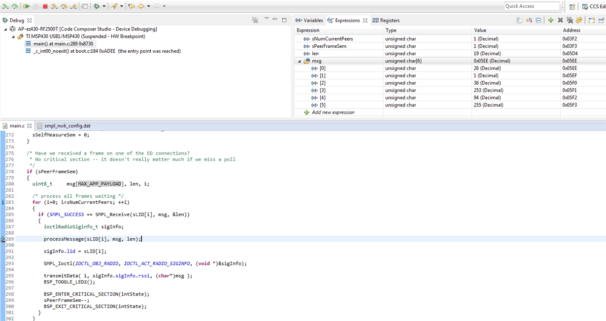
  •  I took the demo program as starting point for working with simpliciti. I want to increase the size of my packets to 19 instead of 6. I have updated the MAX_APP_PAYLOAD and MAX_NWK_PAYLOAD respectively to 19 and 22 in smpl_nwk_config.dat.
    From the debugger when I look at the function call :
    if (SMPL_SUCCESS == SMPL_Receive(sLID[i], msg, &len))

    I have "len" equals to 19 which is fine but my buffer msg size is still 6 ! I have declared msg couple line above like that :
    uint8_t msg[MAX_APP_PAYLOAD];

    Que pasa?

    Thanks.

  • OK found out. Just for posterity. There must be a structure named "msg" in the simpliciti stack. I first hard coded the size of the array, then I declare it as global but with no success. Only renaming it did the trick.
  • Hallo Cedric 40627,

    I don't understand some things:

    -what do you mean with structured named "msg"? In your example above it is already named "msg", right?

    Did you manage to transmit also more then 20 bytes?

    As soon as I change MAX_APP_PAYLOAD in smpl_nwk_config.dat to >20 it is not working anymore, means transmission is not SMPL_SUCCESS.

    The receiving side I used the same command: if (SMPL_SUCCESS == SMPL_Receive(sLID[i], msg, &len))

    - You said u also changed MAX_NWK_PAYLOAD  in smpl_nwk_config.dat. It's not included in my original file from the example project.

    When I add it to the .dat file it is still not working... 

    And why must MAX_NWK_PAYLOAD be 3 more then MAX_APP_PAYLOAD ?

    I really hope someone could help me so that I can enable 50Byte Payload.

    ED.txt
    /* SAMPLE AND CONVERT IN TIMERB ISR, SMPL_SEND IN MAIN LOOP // ON_OFF FUNCTION WITH BUTTON
    Flowchart:
    1: set and start TimerB
    2: if data-array is full do SMPL SEND
    3: go to sleep until TimerB interrupt
    4: in TimerB ISR start AD conversion
    5: in ADC ISR save convert results and disable ADC
    6: goto 2.
    
    TIMINGS: TimerB with ADC ~ 100�s (1MHz)  ~100�s (8MHz) ; SMPL SEND ~8ms(1MHz)  ~3.2ms(8MHz)
    */
    
    #include "bsp.h"
    #include "mrfi.h"
    #include "bsp_leds.h"
    #include "bsp_buttons.h"
    #include "nwk_types.h"
    #include "nwk_api.h"
    #include "nwk_frame.h"
    #include "nwk.h"
    
    #include "msp430x22x4.h"
    #include "vlo_rand.h"
    
    #define WakeupPeriod      36000              // ~3 sec (=36000/(1200/1))
    #define a_d_wakeup_time   36000              // ~3 sec
    ////#define TXPeriod          60000              // ~5 sec  (=7500/(12000/8))
    #define delay_time        4000               // led delay time
    #define debounce_time     6000               // key debounce
    
    //Timer count for time sample
    #define sec1              12000              // ~1 sec
    #define msec100           1200
    #define msec50            600
    #define msec10            120
    #define msec9             108
    #define msec8             96
    #define msec7             84
    #define msec6             72
    #define msec5             60
    #define msec3             36
    #define msec2_5           30
    #define msec1             10 // adapted to real clock
    #define msec09            9
    #define msec08            8
    #define msec07            7
    #define msec03            3
    #define msec02            2
    #define msec01            1
    
    /*
    #define sec40             60000             // ~40 sec
    #define sec30_2           43000             // ~30sec 2 min?
    #define sec30_4           50434             // ~30sec 4 min?
    #define one_hour          5400000
    */
    #define port_delay        10                // 6ms - 1.5 msec
    
    #define status_one        1
    #define status_two        2
    #define status_three      3
    #define status_four       4
    #define status_five       5
    #define status_six        6
    
    #define timer_state_1     1
    #define timer_state_2     2
    #define timer_state_3     3
    #define timer_state_4     4
    #define timer_state_5     5
    #define timer_state_6     6
    
    #define run_voltage       29                // Minimum voltage to execute 2.9V
    #define ad_check_voltage  29
    #define key_down_count    12                // # times to check if button is
                                                // still button pressed
    
    #define battery_time_test 174               // 3 min count at 10 sec for testing
    #define running_on_battery 100              // Tells GUI that it is running on
                                                // battery
    #define xmt_count         400               // # max transmit on battery - 400
    #define LENGTH_MSG 		20
                                                // magic number
    
    #define	ON                1
    #define OFF               0
    
    unsigned int sampletime = msec09;
    unsigned int timer_state;
    //unsigned char change_mode;
    int total_num_conversion = 0;
    //unsigned int battery_ready = 0;
    //unsigned int in_delay = 0;
    
    char num_convert=0;
    char send_flag=0;
    linkID_t linkID1;
    uint8_t  data[LENGTH_MSG] = {0};
    //volatile long temp;
    
    
    int i=0;
    //char status = 0;
    //unsigned int battery_full_flag = 0;
    //unsigned long battery_full_timer = 0;
    
    //unsigned int number_transmits;
    
    void linkTo(void);
    
    //void convert_and_delay(unsigned int BlinkCount);
    
    unsigned int get_voltage(void);
    //void transmit_time_delay(void);
    
    void createRandomAddress(void);
    
    void main (void)
    {
      addr_t lAddr;
      char *Flash_Addr;
      unsigned int current_voltage;
    
    
      WDTCTL = WDTPW + WDTHOLD;                 // Stop WDT
      
      P1DIR |= 0x03;                            // Set P1.0,1 Output
      if( CALBC1_1MHZ == 0xFF && CALDCO_1MHZ == 0xFF &&
          CALBC1_8MHZ == 0xFF && CALDCO_8MHZ == 0xFF )// Do not run if cal values
      {                                         // are erased and set LEDs ON
        P1OUT |= 0x03;                          // Set P1.0,1 High
        __bis_SR_register(LPM4_bits);           // Enter LPM4 if Cal missing
      }
    
      // Blink LED for startup feedback
      P1OUT |= 0x03;                            // Set P1.0,1 High
      __delay_cycles(200000);
      P1OUT &= ~0x03;                           // Set P1.0,1 Low
      
      Flash_Addr = (char *)0x10F0;              // RF Address = 0x10F0
      if( Flash_Addr[0] == 0xFF &&              // Check if device Address is missing
          Flash_Addr[1] == 0xFF &&
          Flash_Addr[2] == 0xFF &&
          Flash_Addr[3] == 0xFF )
      {
        createRandomAddress();                  // Create Random device address at
      }                                         // initial startup if missing
      lAddr.addr[0] = Flash_Addr[0];
      lAddr.addr[1] = Flash_Addr[1];
      lAddr.addr[2] = Flash_Addr[2];
      lAddr.addr[3] = Flash_Addr[3];
      SMPL_Ioctl(IOCTL_OBJ_ADDR, IOCTL_ACT_SET, &lAddr);
    
      BSP_Init();                               // Initialize eZ430 hardware
    
        BCSCTL3 |= LFXT1S_2;                      // LFXT1 = ACLK = VLO
        TBCCTL0 = CCIE;                           // TBCCR0 interrupt enabled
        TBCCR0 =  WakeupPeriod;                   // ~3 sec (=36000/(1200/1))
        TBCTL = TBSSEL_1 + MC_1 + ID_0;           // ACLK, upmode, Divider = 1 !!!!
    
      //status = status_four;                     // Set status to 4
    
      // Initialize SimpliciTI
      while(SMPL_NO_JOIN == SMPL_Init((uint8_t (*)(linkID_t))0))
      {
        __bis_SR_register(LPM3_bits + GIE);     // LPM3 with interrupts enabled
      }
    
      // Put radio to sleep
      SMPL_Ioctl( IOCTL_OBJ_RADIO, IOCTL_ACT_RADIO_SLEEP, "" );
    
    
      BCSCTL1 = CALBC1_8MHZ;                    // Set DCO = 1MHz
      DCOCTL = CALDCO_8MHZ;
    
      // SimpliciTI will change port pin settings as well
      P1DIR = 0xFB;                             // P1.2 (button) = input
      P1OUT = 0x04;                             // P1.2 pullup
      P1REN |= 0x04;                            // P1.2 pullup
      //P1IE |= 0x04;  !!!!!!!!ENABLED IN PROGRAMM     // P1.3 interrupt enabled
      P1IES |= 0x04;                            // P1.3 Hi/lo edge
      P1IFG &= ~0x04;                           // P1.3 IFG cleared
      P2DIR = 0x2E;
      ////P2REN |= 0x01;
      ////P2OUT = 0x01;
      P3DIR |= 0xD0;                            // port 3 set after initilization
      P3OUT &= ~0x30;                           // set up port 3
      P3REN |= 0x20;                            // Enable Pull-Down Res for /Charge
      P4DIR = 0xFF;                             // setup port 4
      P4OUT = 0x00;
    
      timer_state = timer_state_1;              // set timer state to 2 ~ 0.01 sec
      //change_mode = 1;                         // Default GUI display mode set to
                                                // 1 sec
    
    /*  TBCTL |= TBCLR;                           // Clear TBR counter
      TBCCR0 = a_d_wakeup_time;                 // set timer to wakeup time ~ 3 sec
      */
      // added to check if battery voltage stable before linking
      current_voltage = get_voltage();          // get current battery voltage
      if(current_voltage < run_voltage)
      {
        current_voltage = 0;
        while (current_voltage < ad_check_voltage)
        {
         // __bis_SR_register(LPM3_bits + GIE);   // Enter LPM3 w/ interrupts
          current_voltage = get_voltage();
        }
      }
    
      SMPL_Ioctl( IOCTL_OBJ_RADIO, IOCTL_ACT_RADIO_AWAKE, "" );
    
      // unconditional link to AP which is listening due to successful join.
      linkTo();
    }
    
    /*******************************************************************************
     * @fn          linkTo
     ******************************************************************************/
    void linkTo(void)
    {
    	 uint8_t  msg_transmit[LENGTH_MSG] = {0};
    	 uint8_t i=0;
    
      // keep trying to link... Uses Timer B to wake up periodically
      while (SMPL_SUCCESS != SMPL_Link(&linkID1))
      {
        __bis_SR_register(LPM3_bits + GIE);     // LPM3 with interrupts enabled
      }
    
      // put radio to sleep once a successfull connection has been established
      SMPL_Ioctl( IOCTL_OBJ_RADIO, IOCTL_ACT_RADIO_SLEEP, "" );
    
    	   // int TimerTemp;
    	  //TimerTemp = TBCCR0;                       // Save current content of TBCCR0
    	  TBCCTL0 = CCIE;                           // TBCCR0 interrupt enabled
    	  TBCCR0 = sampletime;                      // Set current TBCCR0 delay
    	  //TBCCTL1 = OUTMOD_3;                       // TBCCR1 set/reset
    	  //TBCCR1 = 2;                               // TBCCR1 PWM Duty Cycle
    	  //TBCTL |= TBCLR;                           // Clear TBR counter
    	  TBCTL = TBSSEL_1 + ID_0 + TBCLR;     		// ACLK, upmode, Divider = 1,Clear TBR counter
    	  TBCCTL0 &= ~CCIFG;                        // Clear CCIFG Flag
    	  TBCTL |= MC_1;
    	  total_num_conversion=0;
    	  num_convert=0;
      while(1)
      {
                // Wake radio-up
    
    	if(send_flag)
    	{
    		P2OUT |= 0x02;
    		for (i=0;i<LENGTH_MSG;++i)
    		{
    			msg_transmit[i]=data[i];
    		}
    
    	//data[LENGTH_MSG-2] = (total_num_conversion>>8)&0xFF;
        //data[LENGTH_MSG-1] = total_num_conversion&0xFF;
    
    	      SMPL_Ioctl( IOCTL_OBJ_RADIO, IOCTL_ACT_RADIO_AWAKE, "" );
    
    /*	      for(i=0;i<LENGTH_MSG;++i)
    	      {
    	      	data[i]=65+i&0xFF;
    	      }
    	      data[0]=MAX_APP_PAYLOAD;*/
    	        // Send message
    	      SMPL_Send(linkID1, msg_transmit, sizeof(msg_transmit));
    	     /* if (SMPL_SUCCESS == SMPL_Send(linkID1, data, sizeof(data)))
    	            {
    	      	//P2OUT ^= 0x02;
    	            }*/
    	     // status = status_six;
    
    	      SMPL_Ioctl( IOCTL_OBJ_RADIO, IOCTL_ACT_RADIO_SLEEP, "" );
    	      if(!(P1IN & 0x04))
    	      {
    	    	  TBCCTL0 &= ~CCIE;							//Disable counter interrupt
    	    	  TBCTL &= ~MC_1;							// Stop counter
    	    	  __delay_cycles(3000000);                   // Debounce software delay
    			  while(!(P1IN & 0x04))                   // Loop if button is still pressed
    			  {
    			  }
    			  P1IFG &= ~0x04;                           // P1.2 IFG cleared key interuped
    	    	  P1IE |= 0x04;								//Enable Pin Interrupt
    	    	  __bis_SR_register(LPM3_bits + GIE);       // Enter LPM3
    	      }
    	      send_flag=0;
    
    	      P2OUT &= ~0x02;
    	}
    	 // P1OUT |= 0x01;
    	 // P2OUT ^= 0x02;
          /////////////END SAMPLE AND TRANSMIT
    		  __bis_SR_register(LPM3_bits + GIE);       // Enter LPM3
    
    
      //TBCTL &= ~(MC_1);                         // Stop Timer A
      //TBCCR0 = TimerTemp;
      }
    }
    
    
    /***********************************************************************
    *BEGHDR
    *NAME:        __interrupt void ADC10_ISR(void)
    *DESCRIPTION: ADC10 interrupt service routine
    *INPUTS:      void
    *PROCESSING:  Exit from LPM after interrupt
    *OUTPUTS:     void
    ***********************************************************************/
    #pragma vector=ADC10_VECTOR
    __interrupt void ADC10_ISR(void)
    {
    	//__bic_SR_register_on_exit(LPM0_bits);     // Clear CPUOFF bit from 0(SR)
    	__bic_SR_register_on_exit(LPM3_bits);     // Clear LPM3 bit from 0(SR)
        total_num_conversion++;
     	data[num_convert] =ADC10MEM/100;//(ADC10MEM>>8)&0xFF;// (total_num_conversion>>8)&0xFF;//
        data[num_convert+1] = ADC10MEM%100;//ADC10MEM&0xFF;//total_num_conversion&0xFF;//
    	num_convert=num_convert+2;
        P1OUT &= ~0x01;
        P2OUT &= ~0x08;
    	if (num_convert==LENGTH_MSG)
    	{
    		send_flag=1;
    	    num_convert=0;
    	}
    	ADC10CTL0 &= ~ENC;
        ADC10CTL0 &= ~(REFON + ADC10ON);        // turn off A/D to save power
    
    
        //P1OUT &= ~0x01;
    
    
    }
    
    /*******************************************************************************
    * BEGHDR
    * NAME:        __interrupt void Timer_A (void)
    * DESCRIPTION: Timer A0 interrupt service routine
    * INPUTS:      Void
    * PROCESSING:  Do AD conversion
    * OUTPUTS:     Void
    *******************************************************************************/
    #pragma vector=TIMERB0_VECTOR
    __interrupt void TimerB_ISR (void)
    {
    __bic_SR_register_on_exit(LPM3_bits);     // Clear LPM3 bit from 0(SR)
    
    P1OUT |= 0x01;
    P2OUT |= 0x08;
      // Measure Voltage
      	  ADC10CTL1 = INCH_0;                    // A0 ////AVcc/2
          ADC10CTL0 = SREF_1 + ADC10SHT_3 + REFON + ADC10ON + ADC10IE + REF2_5V;
          __delay_cycles(280);                    // delay to allow reference to settle 35us
          ADC10CTL0 |= ENC + ADC10SC;             // Sampling and conversion start
    
         // __bis_SR_register(LPM0_bits + GIE);     // LPM0 with interrupts enabled
    	TBCCR0=sampletime;  			// set (new) sampletime


    }
    
    
    /*******************************************************************************
    * BEGHDR
    * NAME:        __interrupt void Port_1(void)
    * DESCRIPTION: Port 1 interrupt service routine function key
    * INPUTS:      void
    * PROCESSING:  process the push button to switch to the next time mode
    * OUTPUTS:     void
    ********************************************************************************/
    #pragma vector=PORT1_VECTOR
    __interrupt void Port_1(void)
    {
    
    
    	/*__disable_interrupt();  // Disable Global Interrupts by GIE = 0
    		ADC10CTL0 &= ~(REFON + ADC10ON + ENC + ADC10IE);        // turn off A/D to save power
    		num_convert=0;
    		TBCCTL0 &= ~CCIE;                           // TBCCR0 interrupt enabled*/
    
    /*
    		 switch (timer_state)
    		  {
    		     case timer_state_1:                     // Timer State == 1; 1 Secs
    		    	sampletime=msec09;// measured transmitting(10 ADC Samples � 2 bytes) freq: 103.3Hz => 1033kSa
    		      break;
    		     case timer_state_2:                     // Timer State == 2; 100 ms
    		    	sampletime=msec08;// measured transmitting(10 ADC Samples � 2 bytes) freq: 115.5Hz => 1155kSa
    		      break;
    
    		     case timer_state_3:                     // Timer State == 3; 50 ms
    		    	sampletime=msec07;// measured transmitting(10 ADC Samples � 2 bytes) freq: 130.5Hz => 1305kSa
    		      break;
    
    		     case timer_state_4:                     // Timer State == 4; 10 ms
    		    	 sampletime=msec03;// measured transmitting(10 ADC Samples � 2 bytes) freq: 130.5Hz => 1305kSa //INSTABLE FROM HERE
    		      break;
    
    		     case timer_state_5:                     // Timer State == 5; 5 ms
    		    	  sampletime=msec02;// measured transmitting(10 ADC Samples � 2 bytes) freq: 175.4Hz => 1754kSa
    		      break;
    
    		     case timer_state_6:                     // Timer State == 5; 1 ms
    		    	  sampletime=msec01;// measured transmitting(10 ADC Samples � 2 bytes) freq: 175.4Hz => 1754kSa
    		         timer_state=0;
    		     break;
    		    default:
    		      break;
    		  }
    		 timer_state++;
    		  total_num_conversion=0;
    		  __delay_cycles(3000000);                   // Debounce software delay
    		  while(!(P1IN & 0x04))                   // Loop if button is still pressed
    		  {
    
    		  }*/
    		  __bic_SR_register_on_exit(LPM3_bits);     // Clear LPM3 bit from 0(SR)
    
    
    		  total_num_conversion=0;
    		  P1IE &= ~0x04;							// Disable Pin Interrupt
    		  P1IFG &= ~0x04;                           // P1.2 IFG cleared key interuped
    		  __delay_cycles(3000000);                   // Debounce software delay
    		  while(!(P1IN & 0x04))                   // Loop if button is still pressed
    		  {
    		  }
        	  TBCCTL0 |= CCIE;							//Enable counter interrupt
        	  TBCCTL0 &= ~CCIFG;                        // Clear CCIFG Flag
        	  TBCTL |= MC_1;							// Start counter
    		  /*__enable_interrupt();  // Enable Global Interrupts by GIE = 1
    		  TBCCTL0 |= CCIE;                           // TBCCR0 interrupt enabled
    		  TBCCTL0 &= ~CCIFG;                        // Clear CCIFG Flag	*/
    }
    
    /*******************************************************************************
    * BEGHDR
    *
    * NAME:createRandomAddress()
    *
    * DESCRIPTION: generate random address
    *******************************************************************************/
    void createRandomAddress()
    {
      unsigned int rand, rand2;
      char *Flash_Addr;
      Flash_Addr = (char *)0x10F0;
    
      do
      {
        rand = TI_getRandomIntegerFromVLO();    // first byte can not be 0x00 of 0xFF
      }
      while( (rand & 0xFF00)==0xFF00 || (rand & 0xFF00)==0x0000 );
      rand2 = TI_getRandomIntegerFromVLO();
    
      BCSCTL1 = CALBC1_1MHZ;                    // Set DCO to 1MHz
      DCOCTL = CALDCO_1MHZ;
      FCTL2 = FWKEY + FSSEL0 + FN1;             // MCLK/3 for Flash Timing Generator
      FCTL3 = FWKEY + LOCKA;                    // Clear LOCK & LOCKA bits
      FCTL1 = FWKEY + WRT;                      // Set WRT bit for write operation
    
      Flash_Addr[0]=(rand>>8) & 0xFF;
      Flash_Addr[1]=rand & 0xFF;
      Flash_Addr[2]=(rand2>>8) & 0xFF;
      Flash_Addr[3]=rand2 & 0xFF;
    
      FCTL1 = FWKEY;                            // Clear WRT bit
      FCTL3 = FWKEY + LOCKA + LOCK;             // Set LOCK & LOCKA bit
    }
    
    
    /*******************************************************************************
    * BEGHDR
    * Function:    unsigned int get_voltage(void)
    * DESCRIPTION: Get battery voltage with A/D
    * INPUTS:      void
    * PROCESSING:  Read battery voltage from ADC10 and returns the value
    * OUTPUTS:     Battery voltage from A/D
    *******************************************************************************/
    unsigned int get_voltage(void)
    {
      unsigned int rt_volts;
    
      ADC10CTL1 = INCH_11;                    // AVcc/2
      ADC10CTL0 = SREF_1 + ADC10SHT_2 + REFON + ADC10ON + ADC10IE + REF2_5V;
      __delay_cycles(280);                    // delay to allow reference to settle
      ADC10CTL0 |= ENC + ADC10SC;             // Sampling and conversion start
      __bis_SR_register(LPM0_bits + GIE);     // LPM0 with interrupts enabled
      rt_volts = ADC10MEM;
      ADC10CTL0 &= ~ENC;
      ADC10CTL0 &= ~(REFON + ADC10ON);        // turn off A/D to save power
      rt_volts = (rt_volts*25)/512;
      return (rt_volts);
    }
    
    AD.c
    #include "bsp.h"
    #include "mrfi.h"
    #include "bsp_leds.h"
    #include "bsp_buttons.h"
    #include "nwk_types.h"
    #include "nwk_api.h"
    #include "nwk_frame.h"
    #include "nwk.h"
    
    #include "msp430x22x4.h"
    #include "vlo_rand.h"
    
    //#define MESSAGE_LENGTH 3
    #define LENGTH_MSG 		20
    void TXString( char* string, int length );
    void MCU_Init(void);
    void TXint (int* number);
    void createRandomAddress(void);
    // reserve space for the maximum possible peer Link IDs
    static linkID_t sLID[NUM_CONNECTIONS] = {0};
    static uint8_t  sNumCurrentPeers = 0;
    
    // callback handler
    static uint8_t sCB(linkID_t);
    
    // work loop semaphores
    static uint8_t sPeerFrameSem = 0;
    static uint8_t sJoinSem = 0;
    ////static uint8_t sSelfMeasureSem = 0;
    
    // mode data verbose = default, deg F = default
    char verboseMode = 1;
    char degCMode =0;
    
    int temperature[4] = {0};


    void main (void)
    {
      addr_t lAddr;
      bspIState_t intState;
      char *Flash_Addr;                         // Initialize radio address location
      Flash_Addr = (char *)0x10F0;
    
    
      int i=0;
      int j=0;
      volatile long numbertemp;
      char character[LENGTH_MSG+2]= {0};
    
      WDTCTL = WDTPW + WDTHOLD;                 // Stop WDT
      // delay loop to ensure proper startup before SimpliciTI increases DCO
      // This is typically tailored to the power supply used, and in this case
      // is overkill for safety due to wide distribution.
      __delay_cycles(65000);
    
      if( CALBC1_8MHZ == 0xFF && CALDCO_8MHZ == 0xFF )// Do not run if cal values
      {
        P1DIR |= 0x03;
        BSP_TURN_ON_LED1();
        BSP_TURN_OFF_LED2();
        while(1)
        {
          __delay_cycles(65000);
          BSP_TOGGLE_LED2();
          BSP_TOGGLE_LED1();
        }
      }
    
      BSP_Init();
    
      if( Flash_Addr[0] == 0xFF &&
          Flash_Addr[1] == 0xFF &&
          Flash_Addr[2] == 0xFF &&
          Flash_Addr[3] == 0xFF )
        {
          createRandomAddress();                // Create Random device address at
        }                                       // initial startup if missing
      lAddr.addr[0]=Flash_Addr[0];
      lAddr.addr[1]=Flash_Addr[1];
      lAddr.addr[2]=Flash_Addr[2];
      lAddr.addr[3]=Flash_Addr[3];
    
      //SMPL_Init();
      SMPL_Ioctl(IOCTL_OBJ_ADDR, IOCTL_ACT_SET, &lAddr);
    
      MCU_Init();
    
      SMPL_Init(sCB);
    
    
      // main work loop
      while(1)
      {
        // Wait for the Join semaphore to be set by the receipt of a Join frame from a
        // device that supports and End Device.
    
        if (sJoinSem && (sNumCurrentPeers < NUM_CONNECTIONS))
        {
          // listen for a new connection
          SMPL_LinkListen(&sLID[sNumCurrentPeers]);
          sNumCurrentPeers++;
          BSP_ENTER_CRITICAL_SECTION(intState);
          if (sJoinSem)
          {
            sJoinSem--;
          }
          BSP_EXIT_CRITICAL_SECTION(intState);
        }


        // Have we received a frame on one of the ED connections?
        // No critical section -- it doesn't really matter much if we miss a poll
        if (sPeerFrameSem)
        {
        	P1OUT |= 0x01;
        	P2OUT |= 0x02;
          uint8_t     msg[LENGTH_MSG] = {0}, len, i;
    
          // process all frames waiting
          for (i=0; i<sNumCurrentPeers; ++i)
          {
            if (SMPL_Receive(sLID[i], msg, &len) == SMPL_SUCCESS)
            {
    
              ioctlRadioSiginfo_t sigInfo;
              sigInfo.lid = sLID[i];
              SMPL_Ioctl(IOCTL_OBJ_RADIO, IOCTL_ACT_RADIO_SIGINFO, (void *)&sigInfo);
              ////transmitData( i, (signed char)sigInfo.sigInfo.rssi, (char*)msg );
    
              for (j=0;j<sizeof(msg);++j)
              {
            	  character[j]=msg[j];
              }
              character[LENGTH_MSG] = '\r';
              character[LENGTH_MSG+1] = '\n';
    
          	  TXString( (char*)character,sizeof(character));
    
    
              //BSP_TURN_ON_LED2();               // Toggle LED2 when received packet
              BSP_ENTER_CRITICAL_SECTION(intState);
              sPeerFrameSem--;
              BSP_EXIT_CRITICAL_SECTION(intState);
           	 P1OUT &= ~0x01;
           	 P2OUT &= ~0x02;
              ////__delay_cycles(10000);
              //BSP_TURN_OFF_LED2();
              //BSP_TOGGLE_LED1();
              //BSP_TOGGLE_LED2();
            }
          }
        }
      }
    }


    /*******************************************************************************
    *
    *******************************************************************************/
    void TXString( char* string, int length )
    {
      int pointer;
      for( pointer = 0; pointer < length; pointer++)
      {
        //volatile int i;
    	  UCA0TXBUF = string[pointer];
        while (!(IFG2&UCA0TXIFG));              // USCI_A0 TX buffer ready?
      }
    }
    
    /*******************************************************************************
    *
    *******************************************************************************/
    void MCU_Init()
    {
      BCSCTL1 = CALBC1_8MHZ;                    // Set DCO
      DCOCTL = CALDCO_8MHZ;
    
      BCSCTL3 |= LFXT1S_2;                      // LFXT1 = VLO
      ////TBCCTL0 = CCIE;                           // TCCR0 interrupt enabled
      ////TBCCR0 = 12000;                           // ~1 second
      ////TBCTL = TBSSEL_1 + MC_1;                  // ACLK, upmode
      P1DIR |= 0x03;
      P2DIR |= 0x03;
      P3SEL |= 0x30;                            // P3.4,5 = USCI_A0 TXD/RXD
      UCA0CTL1 = UCSSEL_2;                      // SMCLK
      UCA0BR0 = 0x45;                           // 9600 from 8Mhz  0x41
      UCA0BR1 = 0x00;							// 0x03
      UCA0MCTL = 0xAA; 							// modulation 4 selected UCBRS_2;
      UCA0CTL1 &= ~UCSWRST;                     // **Initialize USCI state machine**
      ////IE2 |= UCA0RXIE;                          // Enable USCI_A0 RX interrupt
      __enable_interrupt();
    }
    
    /*******************************************************************************
    * Runs in ISR context. Reading the frame should be done in the
    * application thread not in the ISR thread.
    *******************************************************************************/
    static uint8_t sCB(linkID_t lid)
    {
      if (lid)
      {
        sPeerFrameSem++;
      }
      else
      {
        sJoinSem++;
      }
      // leave frame to be read by application.
      return 0;
    }
    /*******************************************************************************
    *BEGHDR
    *
    *NAME:createRandomAddress()
    *
    *DESCRIPTION: generate random address
    *
    *******************************************************************************/
    void createRandomAddress(void)
    {
      unsigned int rand, rand2;
      char *Flash_Addr;                         // Initialize radio address location
      Flash_Addr = (char *)0x10F0;
    
      do
      {
        rand = TI_getRandomIntegerFromVLO();    // first byte can not be 0x00 of 0xFF
      }
      while( (rand & 0xFF00)==0xFF00 || (rand & 0xFF00)==0x0000 );
      rand2 = TI_getRandomIntegerFromVLO();
    
      BCSCTL1 = CALBC1_1MHZ;                    // Set DCO to 1MHz
      DCOCTL = CALDCO_1MHZ;
      FCTL2 = FWKEY + FSSEL0 + FN1;             // MCLK/3 for Flash Timing Generator
      FCTL3 = FWKEY + LOCKA;                    // Clear LOCK & LOCKA bits
      FCTL1 = FWKEY + WRT;                      // Set WRT bit for write operation
    
      Flash_Addr[0]=(rand>>8) & 0xFF;
      Flash_Addr[1]=rand & 0xFF;
      Flash_Addr[2]=(rand2>>8) & 0xFF;
      Flash_Addr[3]=rand2 & 0xFF;
    
      FCTL1 = FWKEY;                            // Clear WRT bit
      FCTL3 = FWKEY + LOCKA + LOCK;             // Set LOCK & LOCKA bit
    }