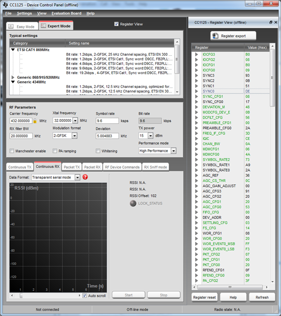
I just started to do some tests with CC1125, but have a problem with the transparent mode not outputting any data on the GPIO-pin as expected.
SPI sommunication with CC1125 is working, I can configure the module, calibrate it and have verified, that I get an RF-signal when used in TX-mode.
The configuration is pretty much directly from SmartRF studio, to get started.
32MHz crystal used, the filter bandwidth etc. is not really important now. This is the configuration output from SmartRF studio.
// RX filter BW = 20.000000 **
// Address config = No address check **
// Packet length = 3 **
// Symbol rate = 9.6 **
// PA ramping = false **
// Performance mode = High Performance **
// Carrier frequency = 432.000000 **
// Bit rate = 9.6 **
// Packet bit length = 0 **
// Whitening = false **
// Manchester enable = false **
// Modulation format = 2-GFSK **
// Packet length mode = Variable **
// Device address = 0 **
// TX power = 15 **
// Deviation = 5.004883 **
CC1125 registers
|
Name |
Address |
Value |
Description |
|
IOCFG3 |
0x0000 |
0xB0 |
GPIO3 IO Pin Configuration |
|
IOCFG2 |
0x0001 |
0x08 |
GPIO2 IO Pin Configuration |
|
IOCFG1 |
0x0002 |
0xB0 |
GPIO1 IO Pin Configuration |
|
IOCFG0 |
0x0003 |
0x09 |
GPIO0 IO Pin Configuration |
|
SYNC_CFG1 |
0x0008 |
0x08 |
Sync Word Detection Configuration Reg. 1 |
|
DEVIATION_M |
0x000A |
0x48 |
Frequency Deviation Configuration |
|
MODCFG_DEV_E |
0x000B |
0x0B |
Modulation Format and Frequency Deviation Configur.. |
|
DCFILT_CFG |
0x000C |
0x56 |
Digital DC Removal Configuration |
|
PREAMBLE_CFG1 |
0x000D |
0x00 |
Preamble Length Configuration Reg. 1 |
|
FREQ_IF_CFG |
0x000F |
0x3D |
RX Mixer Frequency Configuration |
|
IQIC |
0x0010 |
0xCE |
Digital Image Channel Compensation Configuration |
|
CHAN_BW |
0x0011 |
0x0A |
Channel Filter Configuration |
|
MDMCFG1 |
0x0012 |
0x06 |
General Modem Parameter Configuration Reg. 1 |
|
MDMCFG0 |
0x0013 |
0x4A |
General Modem Parameter Configuration Reg. 0 |
|
SYMBOL_RATE2 |
0x0014 |
0x73 |
Symbol Rate Configuration Exponent and Mantissa [1.. |
|
AGC_CS_THR |
0x0018 |
0x0C |
Carrier Sense Threshold Configuration |
|
AGC_CFG1 |
0x001C |
0x20 |
Automatic Gain Control Configuration Reg. 1 |
|
AGC_CFG0 |
0x001D |
0x53 |
Automatic Gain Control Configuration Reg. 0 |
|
FIFO_CFG |
0x001E |
0x00 |
FIFO Configuration |
|
SETTLING_CFG |
0x0020 |
0x03 |
Frequency Synthesizer Calibration and Settling Con.. |
|
FS_CFG |
0x0021 |
0x14 |
Frequency Synthesizer Configuration |
|
WOR_CFG0 |
0x0023 |
0x20 |
eWOR Configuration Reg. 0 |
|
WOR_EVENT0_MSB |
0x0024 |
0xFF |
Event 0 Configuration MSB |
|
WOR_EVENT0_LSB |
0x0025 |
0xF3 |
Event 0 Configuration LSB |
|
PKT_CFG2 |
0x0026 |
0x07 |
Packet Configuration Reg. 2 |
|
PKT_CFG1 |
0x0027 |
0x00 |
Packet Configuration Reg. 1 |
|
PKT_CFG0 |
0x0028 |
0x20 |
Packet Configuration Reg. 0 |
|
RFEND_CFG0 |
0x002A |
0x09 |
RFEND Configuration Reg. 0 |
|
PA_CFG2 |
0x002B |
0x3F |
Power Amplifier Configuration Reg. 2 |
|
PA_CFG0 |
0x002D |
0x7D |
Power Amplifier Configuration Reg. 0 |
|
IF_MIX_CFG |
0x2F00 |
0x00 |
IF Mix Configuration |
|
FREQOFF_CFG |
0x2F01 |
0x22 |
Frequency Offset Correction Configuration |
|
FREQ2 |
0x2F0C |
0x6C |
Frequency Configuration [23:16] |
|
FS_DIG1 |
0x2F12 |
0x00 |
Frequency Synthesizer Digital Reg. 1 |
|
FS_DIG0 |
0x2F13 |
0x5F |
Frequency Synthesizer Digital Reg. 0 |
|
FS_CAL0 |
0x2F17 |
0x0E |
Frequency Synthesizer Calibration Reg. 0 |
|
FS_DIVTWO |
0x2F19 |
0x03 |
Frequency Synthesizer Divide by 2 |
|
FS_DSM0 |
0x2F1B |
0x33 |
FS Digital Synthesizer Module Configuration Reg. 0 |
|
FS_DVC0 |
0x2F1D |
0x17 |
Frequency Synthesizer Divider Chain Configuration .. |
|
FS_PFD |
0x2F1F |
0x50 |
Frequency Synthesizer Phase Frequency Detector Con.. |
|
FS_PRE |
0x2F20 |
0x6E |
Frequency Synthesizer Prescaler Configuration |
|
FS_REG_DIV_CML |
0x2F21 |
0x14 |
Frequency Synthesizer Divider Regulator Configurat.. |
|
FS_SPARE |
0x2F22 |
0xAC |
Frequency Synthesizer Spare |
|
XOSC5 |
0x2F32 |
0x0E |
Crystal Oscillator Configuration Reg. 5 |
|
XOSC3 |
0x2F34 |
0xC7 |
Crystal Oscillator Configuration Reg. 3 |
|
XOSC1 |
0x2F36 |
0x07 |
Crystal Oscillator Configuration Reg. 1 |
|
SERIAL_STATUS |
0x2F91 |
0x08 |
Serial Status |
To get started I really just wanna see all bits, noise etc. and hence all package-handling should be de-activated. I've set:
// Don't use automatic syncword detection
Cc1125ConfigWrite(0X0009,0x03); // SYNC_CFG0 set to 3
// Preamble detection off
Cc1125ConfigWrite(0X000E,0x00); // PREAMBLE_CFG0 set to 0
Serial RX data "should" be connected to GPIO_0, as the GPIO_0 config is set to 9.
The general setup done for CC1125
- Reset CC1125 with command strobe, CC112X_SRES
- Load all config-values that differs from reset-values
(those posted above)
- Run calibration according to CC112x / CC1175 Errata note
- Turn on RX using command strobe, CC112X_SRX
I would expect to see a lot of "noise" or random bits with the data directly connected to GPIO_0, but the pni is constantly low. Anyone seeing an obvious problem?
Doing the exact same as above but with a command strobe for transmit mode in the end, I get the expected RF-output at 432 MHz.


