This thread has been locked.

If you have a related question, please click the "Ask a related question" button in the top right corner. The newly created question will be automatically linked to this question.

Auto Acknowledge + LBT

Other Parts Discussed in Thread: CC1120

Hello, I am trying to send a packet to two different boards and waiting for the reception of both auto acknowledges, one from each of the receivers. I am using LBT in the two receivers in order to not send both Auto ACK back at the same time, but it seems like it is not working. Both receivers are sending the ACK back at the same time, therefore I am losing one of them. I use ID for the two AutoACK to difference in the transmitter between the two Acknowledges sent from the two receivers.

I don't know why I don't get the channel busy when I try to send one of the Auto ACK if the other receiver is sending the Auto ACK and, therefore, busying the channel. My question is: How can I do that process? How can I not lose one of the Auto ACK back?

The threshold for the RSSI value that I am using is -90dbm. The boards are the TrxEB and the RF module the cc1120.

I attach the code for the transmitter and receiver.


Thank you in advance

  • When the two boards receive the same packet this happens at the same time, and they will then try to transmit the ack. at the same time (assuming they are running the same code). Since they start checking if the channel is free at the same time, both transmitters will see a free channel (if nothing else is on the air) and they will enter TX mode (at the same time).

    To avoid this problem all your nodes should have a unique address. Use this address as a seed to generate a random delay which is called before you are trying to transmit the ack. The two boards will start trying to transmit at different times and the LSB algorithm will help avoid collision on the air.

    Siri

  • Hello Siri, thanks for your reply.

    I've been trying to do that but instead of using the address of the node, as a first step, I added a delay in only one of the nodes before the transmission of the ACK. Like this:

    ---------------------------------------------------------------------------------------------------------------------------------------------------

        // Reset packet semaphore
                received = 0;
                rc=cc112xSpiReadReg(CC112X_MARCSTATE, &marcState, 1);
                // Set radio back in RX
                //trxSpiCmdStrobe(CC112X_SRX);

    /************************************send ACK****************************************************************/
                        send=1;
                        if(tx_ID==2){//if(tx_ID==1 || tx_ID==2){
                        
                            __delay_cycles(781250);
                       
                       
                        createPacket(buffer);//createPacket(buffer,packetCountertx);
                            // Write packet to TX FIFO
                       cc112xSpiWriteTxFifo(buffer, sizeof(buffer));
                        }

    ------------------------------------------------------------------------------------------------------------------------------------------------------
    I add that line in red only to the code of one of the nodes, the rest of the code is common for both of them. But the problem still exists and both of them send the ACK at the same time and I lose one of them...

    Any idea of why I still have the same problem?

    Thank you.

  • Hi

    I have modified the EasyLink example on the web. Please see the modified files. The example show how LBT is used and how both ack frames are received correctly. Note that this example is written just to demonstrate that LBT works and is not mean used in an application.

    BR

    SIri

    1881.cc112x_easy_link_rx.c
    //******************************************************************************
    //! @file       cc112x_easy_link_rx.c
    //! @brief      This program sets up an easy link between two trxEB's with
    //!             CC112x EM's connected.
    //!             The program can take any recomended register settings exported
    //!             from SmartRF Studio 7 without any modification with exeption
    //!             from the assumtions decribed below.
    //
    //              Notes: The following asumptions must be fulfilled for
    //              the program to work:
    //
    //                  1.  GPIO2 has to be set up with GPIO2_CFG = 0x06
    //                      PKT_SYNC_RXTX for correct interupt
    //                  2.  Packet engine has to be set up with status bytes enabled
    //                      PKT_CFG1.APPEND_STATUS = 1
    //
    //  Copyright (C) 2013 Texas Instruments Incorporated - http://www.ti.com/
    //
    //  Redistribution and use in source and binary forms, with or without
    //  modification, are permitted provided that the following conditions
    //  are met:
    //
    //      Redistributions of source code must retain the above copyright
    //      notice, this list of conditions and the following disclaimer.
    //
    //      Redistributions in binary form must reproduce the above copyright
    //      notice, this list of conditions and the following disclaimer in the
    //      documentation and/or other materials provided with the distribution.
    //
    //      Neither the name of Texas Instruments Incorporated nor the names of
    //      its contributors may be used to endorse or promote products derived
    //      from this software without specific prior written permission.
    //
    //  THIS SOFTWARE IS PROVIDED BY THE COPYRIGHT HOLDERS AND CONTRIBUTORS
    //  "AS IS" AND ANY EXPRESS OR IMPLIED WARRANTIES, INCLUDING, BUT NOT
    //  LIMITED TO, THE IMPLIED WARRANTIES OF MERCHANTABILITY AND FITNESS FOR
    //  A PARTICULAR PURPOSE ARE DISCLAIMED. IN NO EVENT SHALL THE COPYRIGHT
    //  OWNER OR CONTRIBUTORS BE LIABLE FOR ANY DIRECT, INDIRECT, INCIDENTAL,
    //  SPECIAL, EXEMPLARY, OR CONSEQUENTIAL DAMAGES (INCLUDING, BUT NOT
    //  LIMITED TO, PROCUREMENT OF SUBSTITUTE GOODS OR SERVICES; LOSS OF USE,
    //  DATA, OR PROFITS; OR BUSINESS INTERRUPTION) HOWEVER CAUSED AND ON ANY
    //  THEORY OF LIABILITY, WHETHER IN CONTRACT, STRICT LIABILITY, OR TORT
    //  (INCLUDING NEGLIGENCE OR OTHERWISE) ARISING IN ANY WAY OUT OF THE USE
    //  OF THIS SOFTWARE, EVEN IF ADVISED OF THE POSSIBILITY OF SUCH DAMAGE.
    //*****************************************************************************/
    
    
    /*******************************************************************************
    * INCLUDES
    */
    #include "msp430.h"
    #include "lcd_dogm128_6.h"
    #include "hal_spi_rf_trxeb.h"
    #include "cc112x_spi.h"
    #include "stdlib.h"
    #include "bsp.h"
    #include "bsp_key.h"
    #include "io_pin_int.h"
    #include "bsp_led.h"
    #include "cc112x_easy_link_reg_config.h"
    
    
    /*******************************************************************************
    * DEFINES
    */
    #define ISR_ACTION_REQUIRED 1
    #define ISR_IDLE            0
    #define RX_FIFO_ERROR       0x11
    
    #define GPIO3               0x04
    #define GPIO2               0x08
    #define GPIO0               0x80
    
    #define ADDRESS             0xCD


    /*******************************************************************************
    * LOCAL VARIABLES
    */
    static uint8  packetSemaphore;
    static uint32 packetCounter = 0;
    
    
    /*******************************************************************************
    * STATIC FUNCTIONS
    */
    static void initMCU(void);
    static void registerConfig(void);
    static void manualCalibration(void);
    static void runRX(void);
    static void radioRxTxISR(void);
    static void updateLcd(void);
    static void waitMs(uint16 mSec);
    static void waitUs(uint16 uSec);
    
    
    /*******************************************************************************
    *   @fn         main
    *
    *   @brief      Runs the main routine.
    *
    *   @param      none
    *
    *   @return     none
    */
    void main(void) {
      
        uint8 writeByte; 
    
        // Initialize MCU and peripherals
        initMCU();
    
        // Write radio registers
        registerConfig();
        
        // LBT
        writeByte = 0x10; cc112xSpiWriteReg(CC112X_PKT_CFG2, &writeByte, 1);
        writeByte = 20; cc112xSpiWriteReg(CC112X_AGC_CS_THR, &writeByte, 1);
        
        // Address check   
        writeByte = 0x25; cc112xSpiWriteReg(CC112X_PKT_CFG1, &writeByte, 1);
        writeByte = ADDRESS; cc112xSpiWriteReg(CC112X_DEV_ADDR, &writeByte, 1);
        
    
        // Enter runRX, never coming back
        runRX();
    }
    
    
    /*******************************************************************************
    *   @fn         runRX
    *
    *   @brief      Puts radio in RX and waits for packets. Function assumes
    *               that status bytes are appended in the RX_FIFO
    *               Update packet counter and display for each packet received.
    *
    *   @param      none
    *
    *   @return     none
    */
    static void runRX(void) {
    
        uint8 rxBuffer[128] = {0};
        uint8 rxBytes;
        uint8 marcState;
        uint8 txBuffer[3];
        uint8 rssi1;
        uint8 writeByte; 
        
        txBuffer[0] = 2;            // Length
        txBuffer[1] = 0xEF;         // Address
        txBuffer[2] = ADDRESS;      // Ack
    
        // Connect ISR function to GPIO2
        ioPinIntRegister(IO_PIN_PORT_1, GPIO2, &radioRxTxISR);
    
        // Interrupt on falling edge
        ioPinIntTypeSet(IO_PIN_PORT_1, GPIO2, IO_PIN_FALLING_EDGE);
    
        // Clear ISR flag
        ioPinIntClear(IO_PIN_PORT_1, GPIO2);
    
        // Enable interrupt
        ioPinIntEnable(IO_PIN_PORT_1, GPIO2);
    
        // Update LCD
        updateLcd();
    
        // Calibrate radio according to errata
        manualCalibration();
    
        // Infinite loop
        while(TRUE) {
          
          // Write ACK packet to TX FIFO
          cc112xSpiWriteTxFifo(txBuffer, sizeof(txBuffer));
          
          // Set SYNC_THR = 0B
          writeByte = 0x0B; cc112xSpiWriteReg(CC112X_SYNC_CFG1, &writeByte, 1);
                    
          // Set radio in RX
          trxSpiCmdStrobe(CC112X_SRX);
          
          while(packetSemaphore != ISR_ACTION_REQUIRED);
          
          // Reset packet semaphore
          packetSemaphore = ISR_IDLE;
          
          // Read number of bytes in RX FIFO
          cc112xSpiReadReg(CC112X_NUM_RXBYTES, &rxBytes, 1);
    
          // Check that we have bytes in FIFO
          if(rxBytes != 0) {
    
            // Read MARCSTATE to check for RX FIFO error
            cc112xSpiReadReg(CC112X_MARCSTATE, &marcState, 1);
    
            // Mask out MARCSTATE bits and check if we have a RX FIFO error
            if((marcState & 0x1F) == RX_FIFO_ERROR) {
    
            // Flush RX FIFO
            trxSpiCmdStrobe(CC112X_SFRX);
            } else {
    
              // Read n bytes from RX FIFO
              cc112xSpiReadRxFifo(rxBuffer, rxBytes);
    
              // Check CRC ok (CRC_OK: bit7 in second status byte)
              // This assumes status bytes are appended in RX_FIFO
              // (PKT_CFG1.APPEND_STATUS = 1)
              // If CRC is disabled the CRC_OK field will read 1
              if(rxBuffer[rxBytes - 1] & 0x80) {
    
                // Update packet counter
                packetCounter++;
                
                // Set SYNC_THR = 0
                writeByte = 0x00; cc112xSpiWriteReg(CC112X_SYNC_CFG1, &writeByte, 1);
                trxSpiCmdStrobe(CC112X_SRX);
                
                //Wait for radio to enter RX
                do {
                  cc112xSpiReadReg(CC112X_MARCSTATE, &marcState, 1);
                } while (marcState != 0x6D);
                
                // Wait for RSSI_VALID
                do {
                  cc112xSpiReadReg(CC112X_RSSI0, &rssi1, 1);
                } while (!(rssi1 & 0x01));
                
                waitMs(5);
                
                trxSpiCmdStrobe(CC112X_STX);
                
                while(packetSemaphore != ISR_ACTION_REQUIRED);
                
                // Reset packet semaphore
                packetSemaphore = ISR_IDLE;
                
                // Update LCD
                updateLcd();
              }
            }
          }
        }
    }
    
    /*******************************************************************************
    *   @fn         waitMs
    *
    *   @brief      Busy wait function. Waits the specified number of milliseconds.
    *               Use assumptions about number of clock cycles needed for the
    *               various instructions.
    *
    *               NB! This function is highly dependent on architecture and
    *               compiler!
    *
    *   @param      uint16 mSec - number of milliseconds delay
    *
    *   @return     none
    */
    #pragma optimize=none
    static void waitMs(uint16 mSec) {
        while(mSec-- > 0) {
            waitUs(1000);
        }
    }
    
    /*******************************************************************************
    *   @fn         waitUs
    *
    *   @brief      Busy wait function. Waits the specified number of microseconds.
    *               Use assumptions about number of clock cycles needed for the
    *               various instructions. The duration of one cycle depends on MCLK.
    *               In this HAL it is set to 8 MHz, thus 8 cycles per us.
    *
    *               NB! This function is highly dependent on architecture
    *               and compiler!
    *
    *   @param      uint16 uSec - number of microseconds delay
    *
    *   @return     none
    */
    #pragma optimize=none
    static void waitUs(uint16 uSec) { // 5 cycles for calling
    
        // The least we can wait is 3 usec:
        // ~1 usec for call, 1 for first compare and 1 for return
        while(uSec > 3) {  // 2 cycles for compare
                           // 2 cycles for jump
            NOP();         // 1 cycle for nop
            NOP();         // 1 cycle for nop
            NOP();         // 1 cycle for nop
            NOP();         // 1 cycle for nop
            NOP();         // 1 cycle for nop
            NOP();         // 1 cycle for nop
            NOP();         // 1 cycle for nop
            NOP();         // 1 cycle for nop
            uSec -= 2;     // 1 cycle for optimized decrement
        }
    }                      // 4 cycles for returning
    
    
    /*******************************************************************************
    *   @fn         radioRxTxISR
    *
    *   @brief      ISR for packet handling in RX. Sets packet semaphore
    *               and clears ISR flag
    *
    *   @param      none
    *
    *   @return     none
    */
    static void radioRxTxISR(void) {
    
        // Set packet semaphore
        packetSemaphore = ISR_ACTION_REQUIRED;
    
        // Clear ISR flag
        ioPinIntClear(IO_PIN_PORT_1, GPIO2);
    }
    
    
    /*******************************************************************************
    *   @fn         initMCU
    *
    *   @brief      Initialize MCU and board peripherals
    *
    *   @param      none
    *
    *   @return     none
    */
    static void initMCU(void) {
    
        // Init clocks and I/O
        bspInit(BSP_SYS_CLK_8MHZ);
    
        // Init LEDs
        bspLedInit();
    
        // Init buttons
        bspKeyInit(BSP_KEY_MODE_POLL);
    
        // Initialize SPI interface to LCD (shared with SPI flash)
        bspIoSpiInit(BSP_FLASH_LCD_SPI, BSP_FLASH_LCD_SPI_SPD);
    
        // Init LCD
        lcdInit();
    
        // Instantiate transceiver RF SPI interface to SCLK ~ 4 MHz
        // Input parameter is clockDivider
        // SCLK frequency = SMCLK/clockDivider
        trxRfSpiInterfaceInit(2);
    
        // Enable global interrupt
        _BIS_SR(GIE);
    }
    
    
    /*******************************************************************************
    *   @fn         registerConfig
    *
    *   @brief      Write register settings as given by SmartRF Studio found in
    *               cc112x_easy_link_reg_config.h
    *
    *   @param      none
    *
    *   @return     none
    */
    static void registerConfig(void) {
    
        uint8 writeByte;
    
        // Reset radio
        trxSpiCmdStrobe(CC112X_SRES);
    
        // Write registers to radio
        for(uint16 i = 0;
            i < (sizeof(preferredSettings)/sizeof(registerSetting_t)); i++) {
            writeByte = preferredSettings[i].data;
            cc112xSpiWriteReg(preferredSettings[i].addr, &writeByte, 1);
        }
    }
    
    
    /*******************************************************************************
    *   @fn         updateLcd
    *
    *   @brief      updates LCD buffer and sends buffer to LCD module
    *
    *   @param      none
    *
    *   @return     none
    */
    static void updateLcd(void) {
    
        // Update LDC buffer and send to screen.
        lcdBufferClear(0);
        lcdBufferPrintString(0, "EasyLink Test", 0, eLcdPage0);
        lcdBufferSetHLine(0, 0, LCD_COLS-1, 7);
        lcdBufferPrintString(0, "Received ok:", 0, eLcdPage3);
        lcdBufferPrintInt(0, packetCounter, 70, eLcdPage4);
        lcdBufferPrintString(0, "Packet RX ", 0, eLcdPage7);
        lcdBufferSetHLine(0, 0, LCD_COLS-1, 55);
        lcdBufferInvertPage(0, 0, LCD_COLS, eLcdPage7);
        lcdSendBuffer(0);
    }
    
    
    /*******************************************************************************
    *   @fn         manualCalibration
    *
    *   @brief      Calibrates radio according to CC112x errata
    *
    *   @param      none
    *
    *   @return     none
    */
    #define VCDAC_START_OFFSET 2
    #define FS_VCO2_INDEX 0
    #define FS_VCO4_INDEX 1
    #define FS_CHP_INDEX 2
    static void manualCalibration(void) {
    
        uint8 original_fs_cal2;
        uint8 calResults_for_vcdac_start_high[3];
        uint8 calResults_for_vcdac_start_mid[3];
        uint8 marcstate;
        uint8 writeByte;
    
        // 1) Set VCO cap-array to 0 (FS_VCO2 = 0x00)
        writeByte = 0x00;
        cc112xSpiWriteReg(CC112X_FS_VCO2, &writeByte, 1);
    
        // 2) Start with high VCDAC (original VCDAC_START + 2):
        cc112xSpiReadReg(CC112X_FS_CAL2, &original_fs_cal2, 1);
        writeByte = original_fs_cal2 + VCDAC_START_OFFSET;
        cc112xSpiWriteReg(CC112X_FS_CAL2, &writeByte, 1);
    
        // 3) Calibrate and wait for calibration to be done
        //   (radio back in IDLE state)
        trxSpiCmdStrobe(CC112X_SCAL);
    
        do {
            cc112xSpiReadReg(CC112X_MARCSTATE, &marcstate, 1);
        } while (marcstate != 0x41);
    
        // 4) Read FS_VCO2, FS_VCO4 and FS_CHP register obtained with
        //    high VCDAC_START value
        cc112xSpiReadReg(CC112X_FS_VCO2,
                         &calResults_for_vcdac_start_high[FS_VCO2_INDEX], 1);
        cc112xSpiReadReg(CC112X_FS_VCO4,
                         &calResults_for_vcdac_start_high[FS_VCO4_INDEX], 1);
        cc112xSpiReadReg(CC112X_FS_CHP,
                         &calResults_for_vcdac_start_high[FS_CHP_INDEX], 1);
    
        // 5) Set VCO cap-array to 0 (FS_VCO2 = 0x00)
        writeByte = 0x00;
        cc112xSpiWriteReg(CC112X_FS_VCO2, &writeByte, 1);
    
        // 6) Continue with mid VCDAC (original VCDAC_START):
        writeByte = original_fs_cal2;
        cc112xSpiWriteReg(CC112X_FS_CAL2, &writeByte, 1);
    
        // 7) Calibrate and wait for calibration to be done
        //   (radio back in IDLE state)
        trxSpiCmdStrobe(CC112X_SCAL);
    
        do {
            cc112xSpiReadReg(CC112X_MARCSTATE, &marcstate, 1);
        } while (marcstate != 0x41);
    
        // 8) Read FS_VCO2, FS_VCO4 and FS_CHP register obtained
        //    with mid VCDAC_START value
        cc112xSpiReadReg(CC112X_FS_VCO2,
                         &calResults_for_vcdac_start_mid[FS_VCO2_INDEX], 1);
        cc112xSpiReadReg(CC112X_FS_VCO4,
                         &calResults_for_vcdac_start_mid[FS_VCO4_INDEX], 1);
        cc112xSpiReadReg(CC112X_FS_CHP,
                         &calResults_for_vcdac_start_mid[FS_CHP_INDEX], 1);
    
        // 9) Write back highest FS_VCO2 and corresponding FS_VCO
        //    and FS_CHP result
        if (calResults_for_vcdac_start_high[FS_VCO2_INDEX] >
            calResults_for_vcdac_start_mid[FS_VCO2_INDEX]) {
            writeByte = calResults_for_vcdac_start_high[FS_VCO2_INDEX];
            cc112xSpiWriteReg(CC112X_FS_VCO2, &writeByte, 1);
            writeByte = calResults_for_vcdac_start_high[FS_VCO4_INDEX];
            cc112xSpiWriteReg(CC112X_FS_VCO4, &writeByte, 1);
            writeByte = calResults_for_vcdac_start_high[FS_CHP_INDEX];
            cc112xSpiWriteReg(CC112X_FS_CHP, &writeByte, 1);
        } else {
            writeByte = calResults_for_vcdac_start_mid[FS_VCO2_INDEX];
            cc112xSpiWriteReg(CC112X_FS_VCO2, &writeByte, 1);
            writeByte = calResults_for_vcdac_start_mid[FS_VCO4_INDEX];
            cc112xSpiWriteReg(CC112X_FS_VCO4, &writeByte, 1);
            writeByte = calResults_for_vcdac_start_mid[FS_CHP_INDEX];
            cc112xSpiWriteReg(CC112X_FS_CHP, &writeByte, 1);
        }
    }
    

    4338.cc112x_easy_link_tx.c
    //******************************************************************************
    //! @file       cc112x_easy_link_tx.c
    //! @brief      This program sets up an easy link between two trxEB's with
    //!             CC112x EM's connected.
    //!             The program can take any recomended register settings exported
    //!             from SmartRF Studio 7 without any modification with exeption
    //!             from the assumtions decribed below.
    //
    //              Notes: The following asumptions must be fulfilled for
    //              the program to work:
    //
    //                  1.  GPIO2 has to be set up with GPIO2_CFG = 0x06
    //                      PKT_SYNC_RXTX for correct interupt
    //                  2.  Packet engine has to be set up with status bytes enabled
    //                      PKT_CFG1.APPEND_STATUS = 1
    //
    //  Copyright (C) 2013 Texas Instruments Incorporated - http://www.ti.com/
    //
    //  Redistribution and use in source and binary forms, with or without
    //  modification, are permitted provided that the following conditions
    //  are met:
    //
    //      Redistributions of source code must retain the above copyright
    //      notice, this list of conditions and the following disclaimer.
    //
    //      Redistributions in binary form must reproduce the above copyright
    //      notice, this list of conditions and the following disclaimer in the
    //      documentation and/or other materials provided with the distribution.
    //
    //      Neither the name of Texas Instruments Incorporated nor the names of
    //      its contributors may be used to endorse or promote products derived
    //      from this software without specific prior written permission.
    //
    //  THIS SOFTWARE IS PROVIDED BY THE COPYRIGHT HOLDERS AND CONTRIBUTORS
    //  "AS IS" AND ANY EXPRESS OR IMPLIED WARRANTIES, INCLUDING, BUT NOT
    //  LIMITED TO, THE IMPLIED WARRANTIES OF MERCHANTABILITY AND FITNESS FOR
    //  A PARTICULAR PURPOSE ARE DISCLAIMED. IN NO EVENT SHALL THE COPYRIGHT
    //  OWNER OR CONTRIBUTORS BE LIABLE FOR ANY DIRECT, INDIRECT, INCIDENTAL,
    //  SPECIAL, EXEMPLARY, OR CONSEQUENTIAL DAMAGES (INCLUDING, BUT NOT
    //  LIMITED TO, PROCUREMENT OF SUBSTITUTE GOODS OR SERVICES; LOSS OF USE,
    //  DATA, OR PROFITS; OR BUSINESS INTERRUPTION) HOWEVER CAUSED AND ON ANY
    //  THEORY OF LIABILITY, WHETHER IN CONTRACT, STRICT LIABILITY, OR TORT
    //  (INCLUDING NEGLIGENCE OR OTHERWISE) ARISING IN ANY WAY OUT OF THE USE
    //  OF THIS SOFTWARE, EVEN IF ADVISED OF THE POSSIBILITY OF SUCH DAMAGE.
    //*****************************************************************************/
    
    
    /*******************************************************************************
    * INCLUDES
    */
    #include "msp430.h"
    #include "lcd_dogm128_6.h"
    #include "hal_spi_rf_trxeb.h"
    #include "cc112x_spi.h"
    #include "stdlib.h"
    #include "bsp.h"
    #include "bsp_key.h"
    #include "io_pin_int.h"
    #include "bsp_led.h"
    #include "cc112x_easy_link_reg_config.h"
    
    /*******************************************************************************
    * DEFINES
    */
    #define ISR_ACTION_REQUIRED     1
    #define ISR_IDLE                0
    
    #define PKTLEN                  30  // 1 < PKTLEN < 126
    
    #define GPIO3                   0x04
    #define GPIO2                   0x08
    #define GPIO0                   0x80
    
    #define ADDRESS                 0xEF
    
    
    /*******************************************************************************
    * LOCAL VARIABLES
    */
    static uint8_t  packetSemaphore;
    uint16_t packetCounter = 0;
    
    
    /*******************************************************************************
    * STATIC FUNCTIONS
    */
    static void initMCU(void);
    static void registerConfig(void);
    static void manualCalibration(void);
    static void runTX(void);
    static void createPacket(uint8_t randBuffer[]);
    static void radioTxRxISR(void);
    static void updateLcd(void);
    static void waitMs(uint16 mSec);
    static void waitUs(uint16 uSec);
    
    
    /*******************************************************************************
    *   @fn         main
    *
    *   @brief      Runs the main routine
    *
    *   @param      none
    *
    *   @return     none
    */
    void main(void) {
      
        uint8 writeByte;
    
        // Initialize MCU and peripherals
        initMCU();
    
        // Write radio registers
        registerConfig();
        
        // TXOFF_MODE = RX
        writeByte = 0x30; cc112xSpiWriteReg(CC112X_RFEND_CFG0, &writeByte, 1); 
        
        // RXOFF_MODE = RX
        writeByte = 0x3F; cc112xSpiWriteReg(CC112X_RFEND_CFG1, &writeByte, 1); 
        
        // Max packet length = 2
        writeByte = 0x02; cc112xSpiWriteReg(CC112X_PKT_LEN, &writeByte, 1);
        
        writeByte = 0x25; cc112xSpiWriteReg(CC112X_PKT_CFG1, &writeByte, 1);
        writeByte = ADDRESS; cc112xSpiWriteReg(CC112X_DEV_ADDR, &writeByte, 1);
    
        // Enter runTX, never coming back
        runTX();
    }
    
    
    /*******************************************************************************
    *   @fn         runTX
    *
    *   @brief      Continuously sends packets on button push until button is pushed
    *               again. After the radio has gone into TX the function waits for
    *               interrupt that packet has been sent. Updates packet counter and
    *               display for each packet sent.
    *
    *   @param      none
    *
    *   @return    none
    */
    static void runTX(void) {
    
        // Initialize packet buffer of size PKTLEN + 1
        uint8 txBuffer[PKTLEN+1] = {0};
        uint8 rxBuffer[10];
    
        // Connect ISR function to GPIO2
        ioPinIntRegister(IO_PIN_PORT_1, GPIO2, &radioTxRxISR);
    
        // Interrupt on falling edge
        ioPinIntTypeSet(IO_PIN_PORT_1, GPIO2, IO_PIN_FALLING_EDGE);
    
        // Clear ISR flag
        ioPinIntClear(IO_PIN_PORT_1, GPIO2);
    
        // Enable interrupt
        ioPinIntEnable(IO_PIN_PORT_1, GPIO2);
    
        // Update LCD
        updateLcd();
    
        // Calibrate radio according to errata
        manualCalibration();
    
        // Infinite loop
        while(1) {
    
            // Wait for button push
            if(bspKeyPushed(BSP_KEY_ALL)) {
    
                // Continiously sent packets until button is pressed
                do {
    
                    // Update packet counter
                    packetCounter++;
    
                    // Create a random packet with PKTLEN + 2 byte packet
                    // counter + n x random bytes
                    createPacket(txBuffer);
    
                    // Write packet to TX FIFO
                    cc112xSpiWriteTxFifo(txBuffer, sizeof(txBuffer));
    
                    // Strobe TX to send packet
                    trxSpiCmdStrobe(CC112X_STX);
    
                    // Wait for interrupt that packet has been sent.
                    // (Assumes the GPIO connected to the radioRxTxISR function is
                    // set to GPIOx_CFG = 0x06)
                    while(packetSemaphore != ISR_ACTION_REQUIRED);
    
                    // Clear semaphore flag
                    packetSemaphore = ISR_IDLE;
                    
                    //--------------------------------------------------------------
                    // Packet sent. Radio enters RX automatically to wait for ack. (2)
                    
                    // Wait for interrupt that packet has been received.
                    while(packetSemaphore != ISR_ACTION_REQUIRED);
    
                    // Clear semaphore flag
                    packetSemaphore = ISR_IDLE;
                    
                    // Wait for interrupt that packet has been received.
                    while(packetSemaphore != ISR_ACTION_REQUIRED);
    
                    // Clear semaphore flag
                    packetSemaphore = ISR_IDLE;
                    
                    // Strobe TX to send packet
                    trxSpiCmdStrobe(CC112X_SIDLE);
                    
                    // Read 8 bytes from RX FIFO
                    cc112xSpiReadRxFifo(rxBuffer, 10);
                    
                    if (((rxBuffer[2] == 0xAB) & (rxBuffer[7] == 0xCD)) | 
                        ((rxBuffer[2] == 0xCD) & (rxBuffer[7] == 0xAB))) {
                      
                        // Update LCD
                        updateLcd();
                    }
                    
                    // Wait for a random amount of time between each packet
                    waitMs(3*(rand()%10+3));
                    
                } while (!bspKeyPushed(BSP_KEY_ALL));
            }
        }
    }
    
    
    /*******************************************************************************
    *   @fn         radioTxRXISR
    *
    *   @brief      ISR for packet handling in TX and RX. Sets packet semaphore
    *               and clears ISR flag
    *
    *   @param      none
    *
    *   @return     none
    */
    static void radioTxRxISR(void) {
    
        // Set packet semaphore
        packetSemaphore = ISR_ACTION_REQUIRED;
    
        // Clear ISR flag
        ioPinIntClear(IO_PIN_PORT_1, GPIO2);
    }
    
    
    /*******************************************************************************
    *   @fn         initMCU
    *
    *   @brief      Initialize MCU and board peripherals
    *
    *   @param      none
    *
    *   @return     none
    */
    static void initMCU(void) {
    
        // Init clocks and I/O
        bspInit(BSP_SYS_CLK_8MHZ);
    
        // Init LEDs
        bspLedInit();
    
        // Init buttons
        bspKeyInit(BSP_KEY_MODE_POLL);
    
        // Initialize SPI interface to LCD (shared with SPI flash)
        bspIoSpiInit(BSP_FLASH_LCD_SPI, BSP_FLASH_LCD_SPI_SPD);
    
        // Init LCD
        lcdInit();
    
        // Instantiate transceiver RF SPI interface to SCLK ~ 4 MHz
        // Input parameter is clockDivider
        // SCLK frequency = SMCLK/clockDivider
        trxRfSpiInterfaceInit(2);
    
        // Enable global interrupt
        _BIS_SR(GIE);
    }
    
    
    /*******************************************************************************
    *   @fn         registerConfig
    *
    *   @brief      Write register settings as given by SmartRF Studio found in
    *               cc112x_easy_link_reg_config.h
    *
    *   @param      none
    *
    *   @return     none
    */
    static void registerConfig(void) {
    
        uint8 writeByte;
    
        // Reset radio
        trxSpiCmdStrobe(CC112X_SRES);
    
        // Write registers to radio
        for(uint16 i = 0;
            i < (sizeof(preferredSettings)/sizeof(registerSetting_t)); i++) {
            writeByte = preferredSettings[i].data;
            cc112xSpiWriteReg(preferredSettings[i].addr, &writeByte, 1);
        }
    }
    
    
    /*******************************************************************************
    *   @fn         createPacket
    *
    *   @brief      The packet format is as follows:
    *               |--------------------------------------------------------------|
    *               |           |           |           |         |       |        |
    *               | pktLength | Address   | rndData   |.........|.......| rndData|
    *               |           |           |           |         |       |        |
    *               |--------------------------------------------------------------|
    *                txBuffer[0] txBuffer[1] txBuffer[2]            txBuffer[PKTLEN]
    *
    *   @param       Pointer to start of txBuffer
    *
    *   @return      none
    */
    static void createPacket(uint8 txBuffer[]) {
    
        txBuffer[0] = PKTLEN;               // Length byte
        txBuffer[1] = 0x00;                 // Broadcast address                
    
        // Fill rest of buffer with random bytes
        for(uint8 i = 2; i < (PKTLEN + 1); i++) {
            txBuffer[i] = (uint8)rand();
        }
    }
    
    
    /*******************************************************************************
    *   @fn         updateLcd
    *
    *   @brief      Updates LCD buffer and sends buffer to LCD module
    *
    *   @param      none
    *
    *   @return     none
    */
    static void updateLcd(void) {
    
        // Update LDC buffer and send to screen.
        lcdBufferClear(0);
        lcdBufferPrintString(0, "EasyLink Test", 0, eLcdPage0);
        lcdBufferSetHLine(0, 0, LCD_COLS-1, 7);
        lcdBufferPrintString(0, "Sent packets:", 0, eLcdPage3);
        lcdBufferPrintInt(0, packetCounter, 70, eLcdPage4);
        lcdBufferPrintString(0, "Packet TX" , 0, eLcdPage7);
        lcdBufferSetHLine(0, 0, LCD_COLS-1, 55);
        lcdBufferInvertPage(0, 0, LCD_COLS, eLcdPage7);
        lcdSendBuffer(0);
    }
    
    /*******************************************************************************
    *   @fn         waitMs
    *
    *   @brief      Busy wait function. Waits the specified number of milliseconds.
    *               Use assumptions about number of clock cycles needed for the
    *               various instructions.
    *
    *               NB! This function is highly dependent on architecture and
    *               compiler!
    *
    *   @param      uint16 mSec - number of milliseconds delay
    *
    *   @return     none
    */
    #pragma optimize=none
    static void waitMs(uint16 mSec) {
        while(mSec-- > 0) {
            waitUs(1000);
        }
    }
    
    /*******************************************************************************
    *   @fn         waitUs
    *
    *   @brief      Busy wait function. Waits the specified number of microseconds.
    *               Use assumptions about number of clock cycles needed for the
    *               various instructions. The duration of one cycle depends on MCLK.
    *               In this HAL it is set to 8 MHz, thus 8 cycles per us.
    *
    *               NB! This function is highly dependent on architecture
    *               and compiler!
    *
    *   @param      uint16 uSec - number of microseconds delay
    *
    *   @return     none
    */
    #pragma optimize=none
    static void waitUs(uint16 uSec) { // 5 cycles for calling
    
        // The least we can wait is 3 usec:
        // ~1 usec for call, 1 for first compare and 1 for return
        while(uSec > 3) {  // 2 cycles for compare
                           // 2 cycles for jump
            NOP();         // 1 cycle for nop
            NOP();         // 1 cycle for nop
            NOP();         // 1 cycle for nop
            NOP();         // 1 cycle for nop
            NOP();         // 1 cycle for nop
            NOP();         // 1 cycle for nop
            NOP();         // 1 cycle for nop
            NOP();         // 1 cycle for nop
            uSec -= 2;     // 1 cycle for optimized decrement
        }
    }                      // 4 cycles for returning
    
    /*******************************************************************************
    *   @fn         manualCalibration
    *
    *   @brief      Calibrates radio according to CC112x errata
    *
    *   @param      none
    *
    *   @return     none
    */
    #define VCDAC_START_OFFSET 2
    #define FS_VCO2_INDEX 0
    #define FS_VCO4_INDEX 1
    #define FS_CHP_INDEX 2
    static void manualCalibration(void) {
    
        uint8 original_fs_cal2;
        uint8 calResults_for_vcdac_start_high[3];
        uint8 calResults_for_vcdac_start_mid[3];
        uint8 marcstate;
        uint8 writeByte;
    
        // 1) Set VCO cap-array to 0 (FS_VCO2 = 0x00)
        writeByte = 0x00;
        cc112xSpiWriteReg(CC112X_FS_VCO2, &writeByte, 1);
    
        // 2) Start with high VCDAC (original VCDAC_START + 2):
        cc112xSpiReadReg(CC112X_FS_CAL2, &original_fs_cal2, 1);
        writeByte = original_fs_cal2 + VCDAC_START_OFFSET;
        cc112xSpiWriteReg(CC112X_FS_CAL2, &writeByte, 1);
    
        // 3) Calibrate and wait for calibration to be done
        //   (radio back in IDLE state)
        trxSpiCmdStrobe(CC112X_SCAL);
    
        do {
            cc112xSpiReadReg(CC112X_MARCSTATE, &marcstate, 1);
        } while (marcstate != 0x41);
    
        // 4) Read FS_VCO2, FS_VCO4 and FS_CHP register obtained with 
        //    high VCDAC_START value
        cc112xSpiReadReg(CC112X_FS_VCO2,
                         &calResults_for_vcdac_start_high[FS_VCO2_INDEX], 1);
        cc112xSpiReadReg(CC112X_FS_VCO4,
                         &calResults_for_vcdac_start_high[FS_VCO4_INDEX], 1);
        cc112xSpiReadReg(CC112X_FS_CHP,
                         &calResults_for_vcdac_start_high[FS_CHP_INDEX], 1);
    
        // 5) Set VCO cap-array to 0 (FS_VCO2 = 0x00)
        writeByte = 0x00;
        cc112xSpiWriteReg(CC112X_FS_VCO2, &writeByte, 1);
    
        // 6) Continue with mid VCDAC (original VCDAC_START):
        writeByte = original_fs_cal2;
        cc112xSpiWriteReg(CC112X_FS_CAL2, &writeByte, 1);
    
        // 7) Calibrate and wait for calibration to be done
        //   (radio back in IDLE state)
        trxSpiCmdStrobe(CC112X_SCAL);
    
        do {
            cc112xSpiReadReg(CC112X_MARCSTATE, &marcstate, 1);
        } while (marcstate != 0x41);
    
        // 8) Read FS_VCO2, FS_VCO4 and FS_CHP register obtained 
        //    with mid VCDAC_START value
        cc112xSpiReadReg(CC112X_FS_VCO2, 
                         &calResults_for_vcdac_start_mid[FS_VCO2_INDEX], 1);
        cc112xSpiReadReg(CC112X_FS_VCO4,
                         &calResults_for_vcdac_start_mid[FS_VCO4_INDEX], 1);
        cc112xSpiReadReg(CC112X_FS_CHP,
                         &calResults_for_vcdac_start_mid[FS_CHP_INDEX], 1);
    
        // 9) Write back highest FS_VCO2 and corresponding FS_VCO
        //    and FS_CHP result
        if (calResults_for_vcdac_start_high[FS_VCO2_INDEX] >
            calResults_for_vcdac_start_mid[FS_VCO2_INDEX]) {
            writeByte = calResults_for_vcdac_start_high[FS_VCO2_INDEX];
            cc112xSpiWriteReg(CC112X_FS_VCO2, &writeByte, 1);
            writeByte = calResults_for_vcdac_start_high[FS_VCO4_INDEX];
            cc112xSpiWriteReg(CC112X_FS_VCO4, &writeByte, 1);
            writeByte = calResults_for_vcdac_start_high[FS_CHP_INDEX];
            cc112xSpiWriteReg(CC112X_FS_CHP, &writeByte, 1);
        } else {
            writeByte = calResults_for_vcdac_start_mid[FS_VCO2_INDEX];
            cc112xSpiWriteReg(CC112X_FS_VCO2, &writeByte, 1);
            writeByte = calResults_for_vcdac_start_mid[FS_VCO4_INDEX];
            cc112xSpiWriteReg(CC112X_FS_VCO4, &writeByte, 1);
            writeByte = calResults_for_vcdac_start_mid[FS_CHP_INDEX];
            cc112xSpiWriteReg(CC112X_FS_CHP, &writeByte, 1);
        }
    }


  • Hello Siri, thank you again for your reply.

    there are some things that I don't understand from your code:


    - Why do you put a max packet length of 2 in the TX code? // Max packet length = 2
        writeByte = 0x02; cc112xSpiWriteReg(CC112X_PKT_LEN, &writeByte, 1);

    - Why the ADDRESS is defined as 0xEF? Is the one that is going to be compared with the Address field of the packet received from one of the nodes but in the Rx code the ADDRESS is 0xCD, so is not going to be never the same and therefore, the packet will not be received according to 8.2.1 of the User's guide: "If the address match fails, the packet is discarded"
    - if (((rxBuffer[2] == 0xAB) & (rxBuffer[7] == 0xCD)) | ((rxBuffer[2] == 0xCD) & (rxBuffer[7] == 0xAB)))
    Why in the line above are you checking the rxBuffer [7], in the receiver part you are putting the address of the node in rxBuffer[2] but i don't know what is it in rxBuffer[7] and, therefore, why are you checking it? Can you explain me why are you checking both, how would be the rxBuffer structure in the tx part after receiving both ACK?

    -Why don't you implement LBT for the tx part?

    Can you please help me?

    Thank you in advance

  • Hi

    The receiver sends ACK packets that are 3 bytes long: A length byte (0x02), the address of the transmitter (0xEF) and its own address (0xAB or 0xCD). The transmitter uses length filtering and sets max packet length to 2 since these are the only packet it is interested in receiving.

    When talking to several nodes it is natural that all nodes have their own address. That way it will only receive the messages with the correct address (or broadcast messages). I also send the address back in the ACK packet so that the transmitter knows which nodes have received the message.

    There are two receivers that are sending ACK packets. The receivers have address 0xAB and 0xCD. The transmitter has address 0xEF.

    The ACK packets look like this:

    0x02, 0xEF, 0xAB (from receiver 0xAB) and

    0x02, 0xEF, 0xCD (from receiver 0xCD.

    The transmitter has “append status” enabled and two packets are received before it checks that both ACK messages has been received.

    In the TXFIFO you will have this:

    0x02, 0xEF, 0xAB, status, status, 0x02, 0xEF, 0xCD, status, status or

    0x02, 0xEF, 0xCD, status, status, 0x02, 0xEF, 0xAB, status, status

    You can off course use LBT on the transmitter as well. This was just a simple example to show you that the LBT function works as stated in the user guide.

    Siri

  • Ok, I understand now.

    But I am trying the code, exactly as you put it and it doesn't work, both receivers send the ACKs but the transmitter only receives one of them, if I put a delay before strobing the tx command in one of the receivers it works but without that delay it doesn't, that delay has to be at least of 70ms, which seems extremely long for me... Can you please tell me what I am doing wrong? It looks like the LBT is not working or maybe it is because both receivers check the channel at the same time and they see the channel free at the same time...
    Thanks in advance

  • Hi

    It is hard for me to say what the problem is as long as everything works fine here. I would recommend that you use a logic analyzer and monitor all three units to figure out what is going wrong. You can output the PKT_SYNC_RXTX signal + MARC_2PIN_STATUS[1] [0] on the 3 GPIO to find out when the chip is in RX and TX and when packets are sent/received.

    Siri

  • Hi Siri,

    I tried your code but it did not work at first time. Then i recognized that any rx/tx end mode is specified in RX code.

    I got positive results after writing below registers.

          // TXOFF_MODE = RX

       writeByte = 0x38; cc112xSpiWriteReg(CC112X_RFEND_CFG0, &writeByte, 1);

       //RX Off mode=TX

       writeByte = 0x2E; cc112xSpiWriteReg(CC112X_RFEND_CFG1, &writeByte, 1);

    Application is still getting stuck on 25th packet but never mind, this is not something i want to ask.

    I would like to combine Sniff mode and auto acknowledge. To achieve that i set WOR mode as legacy and RXOFF_MODE as TX.

    Is it possible to use auto ack. with eWOR? If yes, it means there are some missing points, could you give me a clue?

    1120_wor_ack.c
    //******************************************************************************
    //! @file       cc112x_easy_link_rx.c
    //! @brief      This program sets up an easy link between two trxEB's with
    //!             CC112x EM's connected.
    //!             The program can take any recomended register settings exported
    //!             from SmartRF Studio 7 without any modification with exeption
    //!             from the assumtions decribed below.
    //
    //              Notes: The following asumptions must be fulfilled for
    //              the program to work:
    //
    //                  1.  GPIO2 has to be set up with GPIO2_CFG = 0x06
    //                      PKT_SYNC_RXTX for correct interupt
    //                  2.  Packet engine has to be set up with status bytes enabled
    //                      PKT_CFG1.APPEND_STATUS = 1
    //
    //  Copyright (C) 2013 Texas Instruments Incorporated - http://www.ti.com/
    //
    //  Redistribution and use in source and binary forms, with or without
    //  modification, are permitted provided that the following conditions
    //  are met:
    //
    //      Redistributions of source code must retain the above copyright
    //      notice, this list of conditions and the following disclaimer.
    //
    //      Redistributions in binary form must reproduce the above copyright
    //      notice, this list of conditions and the following disclaimer in the
    //      documentation and/or other materials provided with the distribution.
    //
    //      Neither the name of Texas Instruments Incorporated nor the names of
    //      its contributors may be used to endorse or promote products derived
    //      from this software without specific prior written permission.
    //
    //  THIS SOFTWARE IS PROVIDED BY THE COPYRIGHT HOLDERS AND CONTRIBUTORS
    //  "AS IS" AND ANY EXPRESS OR IMPLIED WARRANTIES, INCLUDING, BUT NOT
    //  LIMITED TO, THE IMPLIED WARRANTIES OF MERCHANTABILITY AND FITNESS FOR
    //  A PARTICULAR PURPOSE ARE DISCLAIMED. IN NO EVENT SHALL THE COPYRIGHT
    //  OWNER OR CONTRIBUTORS BE LIABLE FOR ANY DIRECT, INDIRECT, INCIDENTAL,
    //  SPECIAL, EXEMPLARY, OR CONSEQUENTIAL DAMAGES (INCLUDING, BUT NOT
    //  LIMITED TO, PROCUREMENT OF SUBSTITUTE GOODS OR SERVICES; LOSS OF USE,
    //  DATA, OR PROFITS; OR BUSINESS INTERRUPTION) HOWEVER CAUSED AND ON ANY
    //  THEORY OF LIABILITY, WHETHER IN CONTRACT, STRICT LIABILITY, OR TORT
    //  (INCLUDING NEGLIGENCE OR OTHERWISE) ARISING IN ANY WAY OUT OF THE USE
    //  OF THIS SOFTWARE, EVEN IF ADVISED OF THE POSSIBILITY OF SUCH DAMAGE.
    //*****************************************************************************/
    
    
    /*******************************************************************************
    * INCLUDES
    */
    #include "msp430.h"
    #include "lcd_dogm128_6.h"
    #include "hal_spi_rf_trxeb.h"
    #include "cc112x_spi.h"
    #include "stdlib.h"
    #include "bsp.h"
    #include "bsp_key.h"
    #include "io_pin_int.h"
    #include "bsp_led.h"
    #include "cc112x_easy_link_reg_config.h"
    
    
    /*******************************************************************************
    * DEFINES
    */
    #define ISR_ACTION_REQUIRED 1
    #define ISR_IDLE            0
    #define RX_FIFO_ERROR       0x11
    
    #define GPIO3               0x04
    #define GPIO2               0x08
    #define GPIO0               0x80
    
    #define ADDRESS             0xCD


    /*******************************************************************************
    * LOCAL VARIABLES
    */
    static uint8  packetSemaphore;
    static uint32 packetCounter = 0;
    
    
    /*******************************************************************************
    * STATIC FUNCTIONS
    */
    static void initMCU(void);
    static void registerConfig(void);
    static void manualCalibration(void);
    static void runRX(void);
    static void radioRxTxISR(void);
    static void updateLcd(void);
    static void waitMs(uint16 mSec);
    static void waitUs(uint16 uSec);
    static void calibrateRCOsc(void);
    
    
    /*******************************************************************************
    *   @fn         main
    *
    *   @brief      Runs the main routine.
    *
    *   @param      none
    *
    *   @return     none
    */
    void main(void) {
      
        uint8 writeByte; 
    
        // Initialize MCU and peripherals
        initMCU();
    
        // Write radio registers
        registerConfig();
        
        // LBT
        writeByte = 0x10; cc112xSpiWriteReg(CC112X_PKT_CFG2, &writeByte, 1); //lbt
        writeByte = 20; cc112xSpiWriteReg(CC112X_AGC_CS_THR, &writeByte, 1); //lbt
        
        // Address check   
        writeByte = 0x25; cc112xSpiWriteReg(CC112X_PKT_CFG1, &writeByte, 1);
        writeByte = ADDRESS; cc112xSpiWriteReg(CC112X_DEV_ADDR, &writeByte, 1);
        
           // TXOFF_MODE = RX
        writeByte = 0x38; cc112xSpiWriteReg(CC112X_RFEND_CFG0, &writeByte, 1); 
        
        //RX Off mode=TX
        writeByte = 0x2F; cc112xSpiWriteReg(CC112X_RFEND_CFG1, &writeByte, 1);
    
        // Enter runRX, never coming back
        runRX();
    }
    
    
    /*******************************************************************************
    *   @fn         runRX
    *
    *   @brief      Puts radio in RX and waits for packets. Function assumes
    *               that status bytes are appended in the RX_FIFO
    *               Update packet counter and display for each packet received.
    *
    *   @param      none
    *
    *   @return     none
    */
    static void runRX(void) {
    
        uint8 rxBuffer[128] = {0};
        uint8 rxBytes;
        uint8 marcState;
        uint8 txBuffer[3];
        uint8 rssi1;
        uint8 writeByte; 
        
        txBuffer[0] = 2;            // Length
        txBuffer[1] = 0xEF;         // Address
        txBuffer[2] = ADDRESS;      // Ack
    
        // Connect ISR function to GPIO2
        ioPinIntRegister(IO_PIN_PORT_1, GPIO2, &radioRxTxISR);
    
        // Interrupt on falling edge
        ioPinIntTypeSet(IO_PIN_PORT_1, GPIO2, IO_PIN_FALLING_EDGE);
    
        // Clear ISR flag
        ioPinIntClear(IO_PIN_PORT_1, GPIO2);
    
        // Enable interrupt
        ioPinIntEnable(IO_PIN_PORT_1, GPIO2);
    
        // Update LCD
        updateLcd();
    
        // Calibrate radio according to errata
        manualCalibration();
    
        calibrateRCOsc();
        
        // Infinite loop
        while(TRUE) {
          
          
          // Write ACK packet to TX FIFO
          cc112xSpiWriteTxFifo(txBuffer, sizeof(txBuffer));
          
          // Set SYNC_THR = 0B
          //writeByte = 0x0B; cc112xSpiWriteReg(CC112X_SYNC_CFG1, &writeByte, 1); //lbt
                    
          // Set radio in RX
          
          //trxSpiCmdStrobe(CC112X_SRX);
          trxSpiCmdStrobe(CC112X_SWORRST);
          trxSpiCmdStrobe(CC112X_SWOR);
           
          //__low_power_mode_3();
          
          while(packetSemaphore != ISR_ACTION_REQUIRED);
          
          // Reset packet semaphore
          packetSemaphore = ISR_IDLE;
          
          
           //Packet received. Radio enters TX automatically to send for ack.
          
            while(packetSemaphore != ISR_ACTION_REQUIRED);
                
                // Reset packet semaphore
            packetSemaphore = ISR_IDLE;
          
            while(packetSemaphore != ISR_ACTION_REQUIRED);
            // Reset packet semaphore
            packetSemaphore = ISR_IDLE;     
            
            //while((trxSpiCmdStrobe(CC112X_SNOP)& 0xF0) != 0x00);
          
            // Strobe IDLE to read registers
          trxSpiCmdStrobe(CC112X_SIDLE);
            
          // Read number of bytes in RX FIFO
          cc112xSpiReadReg(CC112X_NUM_RXBYTES, &rxBytes, 1);
    
          // Check that we have bytes in FIFO
          if(rxBytes != 0) {
    
            // Read MARCSTATE to check for RX FIFO error
            cc112xSpiReadReg(CC112X_MARCSTATE, &marcState, 1);
    
            // Mask out MARCSTATE bits and check if we have a RX FIFO error
            if((marcState & 0x1F) == RX_FIFO_ERROR) {
    
            // Flush RX FIFO
            trxSpiCmdStrobe(CC112X_SFRX);
            } else {
    
              // Read n bytes from RX FIFO
              cc112xSpiReadRxFifo(rxBuffer, rxBytes);
    
              // Check CRC ok (CRC_OK: bit7 in second status byte)
              // This assumes status bytes are appended in RX_FIFO
              // (PKT_CFG1.APPEND_STATUS = 1)
              // If CRC is disabled the CRC_OK field will read 1
              if(rxBuffer[rxBytes - 1] & 0x80) {
    
                // Update packet counter
                packetCounter++;
                
                  do {
                  cc112xSpiReadReg(CC112X_MARCSTATE, &marcState, 1);
                } while (marcState != 0x6D);
                
              /*  // Set SYNC_THR = 0
                writeByte = 0x00; cc112xSpiWriteReg(CC112X_SYNC_CFG1, &writeByte, 1);
                trxSpiCmdStrobe(CC112X_SRX);
                
                //Wait for radio to enter RX
                do {
                  cc112xSpiReadReg(CC112X_MARCSTATE, &marcState, 1);
                } while (marcState != 0x6D);
                
                // Wait for RSSI_VALID
                do {
                  cc112xSpiReadReg(CC112X_RSSI0, &rssi1, 1);
                } while (!(rssi1 & 0x01));*/
    
                
                //while((trxSpiCmdStrobe(CC112X_SNOP)& 0xF0) != 0x00);
                // Update LCD
                updateLcd();
              }
              waitMs(3*(rand()%10+3));
            }
          }
        }
    }
    
    /*******************************************************************************
    *   @fn         waitMs
    *
    *   @brief      Busy wait function. Waits the specified number of milliseconds.
    *               Use assumptions about number of clock cycles needed for the
    *               various instructions.
    *
    *               NB! This function is highly dependent on architecture and
    *               compiler!
    *
    *   @param      uint16 mSec - number of milliseconds delay
    *
    *   @return     none
    */
    #pragma optimize=none
    static void waitMs(uint16 mSec) {
        while(mSec-- > 0) {
            waitUs(1000);
        }
    }
    
    /*******************************************************************************
    *   @fn         waitUs
    *
    *   @brief      Busy wait function. Waits the specified number of microseconds.
    *               Use assumptions about number of clock cycles needed for the
    *               various instructions. The duration of one cycle depends on MCLK.
    *               In this HAL it is set to 8 MHz, thus 8 cycles per us.
    *
    *               NB! This function is highly dependent on architecture
    *               and compiler!
    *
    *   @param      uint16 uSec - number of microseconds delay
    *
    *   @return     none
    */
    #pragma optimize=none
    static void waitUs(uint16 uSec) { // 5 cycles for calling
    
        // The least we can wait is 3 usec:
        // ~1 usec for call, 1 for first compare and 1 for return
        while(uSec > 3) {  // 2 cycles for compare
                           // 2 cycles for jump
            NOP();         // 1 cycle for nop
            NOP();         // 1 cycle for nop
            NOP();         // 1 cycle for nop
            NOP();         // 1 cycle for nop
            NOP();         // 1 cycle for nop
            NOP();         // 1 cycle for nop
            NOP();         // 1 cycle for nop
            NOP();         // 1 cycle for nop
            uSec -= 2;     // 1 cycle for optimized decrement
        }
    }                      // 4 cycles for returning
    
    /*******************************************************************************
    *   @fn         calibrateRcOsc
    *
    *   @brief      Calibrates the RC oscillator used for the eWOR timer. When this
    *               function is called, WOR_CFG0.RC_PD must be 0
    *
    *   @param      none
    *
    *   @return     none
    */
    static void calibrateRCOsc(void) {
    
        uint8 temp;
    
        // Read current register value
        cc112xSpiReadReg(CC112X_WOR_CFG0, &temp,1);
    
        // Mask register bit fields and write new values
        temp = (temp & 0xF9) | (0x02 << 1);
    
        // Write new register value
        cc112xSpiWriteReg(CC112X_WOR_CFG0, &temp,1);
    
        // Strobe IDLE to calibrate the RCOSC
        trxSpiCmdStrobe(CC112X_SIDLE);
    
        // Disable RC calibration
        temp = (temp & 0xF9) | (0x00 << 1);
        cc112xSpiWriteReg(CC112X_WOR_CFG0, &temp, 1);
    }
    /*******************************************************************************
    *   @fn         radioRxTxISR
    *
    *   @brief      ISR for packet handling in RX. Sets packet semaphore
    *               and clears ISR flag
    *
    *   @param      none
    *
    *   @return     none
    */
    static void radioRxTxISR(void) {
    
        // Set packet semaphore
        packetSemaphore = ISR_ACTION_REQUIRED;
    
        // Clear ISR flag
        ioPinIntClear(IO_PIN_PORT_1, GPIO2);
    }
    
    
    /*******************************************************************************
    *   @fn         initMCU
    *
    *   @brief      Initialize MCU and board peripherals
    *
    *   @param      none
    *
    *   @return     none
    */
    static void initMCU(void) {
    
        // Init clocks and I/O
        bspInit(BSP_SYS_CLK_8MHZ);
    
        // Init LEDs
        bspLedInit();
    
        // Init buttons
        bspKeyInit(BSP_KEY_MODE_POLL);
    
        // Initialize SPI interface to LCD (shared with SPI flash)
        bspIoSpiInit(BSP_FLASH_LCD_SPI, BSP_FLASH_LCD_SPI_SPD);
    
        // Init LCD
        lcdInit();
    
        // Instantiate transceiver RF SPI interface to SCLK ~ 4 MHz
        // Input parameter is clockDivider
        // SCLK frequency = SMCLK/clockDivider
        trxRfSpiInterfaceInit(2);
    
        // Enable global interrupt
        _BIS_SR(GIE);
    }
    
    
    /*******************************************************************************
    *   @fn         registerConfig
    *
    *   @brief      Write register settings as given by SmartRF Studio found in
    *               cc112x_easy_link_reg_config.h
    *
    *   @param      none
    *
    *   @return     none
    */
    static void registerConfig(void) {
    
        uint8 writeByte;
    
        // Reset radio
        trxSpiCmdStrobe(CC112X_SRES);
    
        // Write registers to radio
        for(uint16 i = 0;
            i < (sizeof(preferredSettings)/sizeof(registerSetting_t)); i++) {
            writeByte = preferredSettings[i].data;
            cc112xSpiWriteReg(preferredSettings[i].addr, &writeByte, 1);
        }
    }
    
    
    /*******************************************************************************
    *   @fn         updateLcd
    *
    *   @brief      updates LCD buffer and sends buffer to LCD module
    *
    *   @param      none
    *
    *   @return     none
    */
    static void updateLcd(void) {
    
        // Update LDC buffer and send to screen.
        lcdBufferClear(0);
        lcdBufferPrintString(0, "EasyLink Test", 0, eLcdPage0);
        lcdBufferSetHLine(0, 0, LCD_COLS-1, 7);
        lcdBufferPrintString(0, "Received ok:", 0, eLcdPage3);
        lcdBufferPrintInt(0, packetCounter, 70, eLcdPage4);
        lcdBufferPrintString(0, "Packet RX ", 0, eLcdPage7);
        lcdBufferSetHLine(0, 0, LCD_COLS-1, 55);
        lcdBufferInvertPage(0, 0, LCD_COLS, eLcdPage7);
        lcdSendBuffer(0);
    }
    
    
    /*******************************************************************************
    *   @fn         manualCalibration
    *
    *   @brief      Calibrates radio according to CC112x errata
    *
    *   @param      none
    *
    *   @return     none
    */
    #define VCDAC_START_OFFSET 2
    #define FS_VCO2_INDEX 0
    #define FS_VCO4_INDEX 1
    #define FS_CHP_INDEX 2
    static void manualCalibration(void) {
    
        uint8 original_fs_cal2;
        uint8 calResults_for_vcdac_start_high[3];
        uint8 calResults_for_vcdac_start_mid[3];
        uint8 marcstate;
        uint8 writeByte;
    
        // 1) Set VCO cap-array to 0 (FS_VCO2 = 0x00)
        writeByte = 0x00;
        cc112xSpiWriteReg(CC112X_FS_VCO2, &writeByte, 1);
    
        // 2) Start with high VCDAC (original VCDAC_START + 2):
        cc112xSpiReadReg(CC112X_FS_CAL2, &original_fs_cal2, 1);
        writeByte = original_fs_cal2 + VCDAC_START_OFFSET;
        cc112xSpiWriteReg(CC112X_FS_CAL2, &writeByte, 1);
    
        // 3) Calibrate and wait for calibration to be done
        //   (radio back in IDLE state)
        trxSpiCmdStrobe(CC112X_SCAL);
    
        do {
            cc112xSpiReadReg(CC112X_MARCSTATE, &marcstate, 1);
        } while (marcstate != 0x41);
    
        // 4) Read FS_VCO2, FS_VCO4 and FS_CHP register obtained with
        //    high VCDAC_START value
        cc112xSpiReadReg(CC112X_FS_VCO2,
                         &calResults_for_vcdac_start_high[FS_VCO2_INDEX], 1);
        cc112xSpiReadReg(CC112X_FS_VCO4,
                         &calResults_for_vcdac_start_high[FS_VCO4_INDEX], 1);
        cc112xSpiReadReg(CC112X_FS_CHP,
                         &calResults_for_vcdac_start_high[FS_CHP_INDEX], 1);
    
        // 5) Set VCO cap-array to 0 (FS_VCO2 = 0x00)
        writeByte = 0x00;
        cc112xSpiWriteReg(CC112X_FS_VCO2, &writeByte, 1);
    
        // 6) Continue with mid VCDAC (original VCDAC_START):
        writeByte = original_fs_cal2;
        cc112xSpiWriteReg(CC112X_FS_CAL2, &writeByte, 1);
    
        // 7) Calibrate and wait for calibration to be done
        //   (radio back in IDLE state)
        trxSpiCmdStrobe(CC112X_SCAL);
    
        do {
            cc112xSpiReadReg(CC112X_MARCSTATE, &marcstate, 1);
        } while (marcstate != 0x41);
    
        // 8) Read FS_VCO2, FS_VCO4 and FS_CHP register obtained
        //    with mid VCDAC_START value
        cc112xSpiReadReg(CC112X_FS_VCO2,
                         &calResults_for_vcdac_start_mid[FS_VCO2_INDEX], 1);
        cc112xSpiReadReg(CC112X_FS_VCO4,
                         &calResults_for_vcdac_start_mid[FS_VCO4_INDEX], 1);
        cc112xSpiReadReg(CC112X_FS_CHP,
                         &calResults_for_vcdac_start_mid[FS_CHP_INDEX], 1);
    
        // 9) Write back highest FS_VCO2 and corresponding FS_VCO
        //    and FS_CHP result
        if (calResults_for_vcdac_start_high[FS_VCO2_INDEX] >
            calResults_for_vcdac_start_mid[FS_VCO2_INDEX]) {
            writeByte = calResults_for_vcdac_start_high[FS_VCO2_INDEX];
            cc112xSpiWriteReg(CC112X_FS_VCO2, &writeByte, 1);
            writeByte = calResults_for_vcdac_start_high[FS_VCO4_INDEX];
            cc112xSpiWriteReg(CC112X_FS_VCO4, &writeByte, 1);
            writeByte = calResults_for_vcdac_start_high[FS_CHP_INDEX];
            cc112xSpiWriteReg(CC112X_FS_CHP, &writeByte, 1);
        } else {
            writeByte = calResults_for_vcdac_start_mid[FS_VCO2_INDEX];
            cc112xSpiWriteReg(CC112X_FS_VCO2, &writeByte, 1);
            writeByte = calResults_for_vcdac_start_mid[FS_VCO4_INDEX];
            cc112xSpiWriteReg(CC112X_FS_VCO4, &writeByte, 1);
            writeByte = calResults_for_vcdac_start_mid[FS_CHP_INDEX];
            cc112xSpiWriteReg(CC112X_FS_CHP, &writeByte, 1);
        }
    }
    
    cc112x_easy_link_reg_config.h

  • Hi

    It is not possible to use auto ack together with RX Sniff mode as the FIFO pointers do not have retention in SLEEP.

    BR

    Siri

  • Hello again,

    I have one more question about auto ack.

    In our application, first we assign addresses with the help of transmitter and then start communication.
    While assigning addresses, i set CC112X_PKT_CFG1 as 0x05 because there is no value at CC112X_DEV_ADDR register.
    In this case by setting registers as below and i achieved to receive auto ack.

    Receiver:
    // TXOFF_MODE = RX
    writeByte = 0x38; cc112xSpiWriteReg(CC112X_RFEND_CFG0, &writeByte, 1);

    //RX Off mode=TX
    writeByte = 0x2E; cc112xSpiWriteReg(CC112X_RFEND_CFG1, &writeByte, 1);

    Transmitter:

    // TXOFF_MODE = RX
    writeByte = 0x38; cc112xSpiWriteReg(CC112X_RFEND_CFG0, &writeByte, 1);

    // RXOFF_MODE = RX
    writeByte = 0x3F; cc112xSpiWriteReg(CC112X_RFEND_CFG1, &writeByte, 1);

    // Max packet length = 2
    writeByte = 0x02; cc112xSpiWriteReg(CC112X_PKT_LEN, &writeByte, 1);

    After assigning addresses (and also flushing fifo registers), i could not receive with same logic.
    In fact, transmitter receives auto ack packet but if statement always returns false. Since we do not have LCD on our module, i can not see received packet.

    Here are the ack packet and if statement;

    Receiver:

    uint8 txTest[3];

    cc112xSpiWriteTxFifo(txTest, sizeof(txTest));

    txTest[0] = 2; // Length
    txTest[1] = 0xA1; // Transmitter address (client address)
    txTest[2] = 0xAA; // Ack (own address)

    Transmitter:

    cc112xSpiReadRxFifo(rxBuffer, 3);

    if(rxBuffer[2] == 0xAA)
    {....
    } -->returns false?


    I am sure, ack. packet is written before RX mode and ack packet is received by transmitter. Let me ask my questions.

    1. If the transceiver has a value at address field, do we have to enable 'address check' for auto ack? I set CC112X_PKT_CFG1 as 0x15 (also as 0x05) but it didn't work.

    2. Does ack packet has to include length, transmitter address and it's own address or can we write arbitrary packets? Even i write ack packet in that way, it didn't work.

    3. What is the possible solution of this problem?

    Thanks.
  • Hi

    It is not enough to write to the DEV_ADDR register. You also need to enable address filtering by setting PKT_CFG1.ADDRE_CHECK_CFG != 0.

    The ACK packet needs to have the length as the first byte (if using variable packet length mode) and address as the second byte, when doing address filtering.

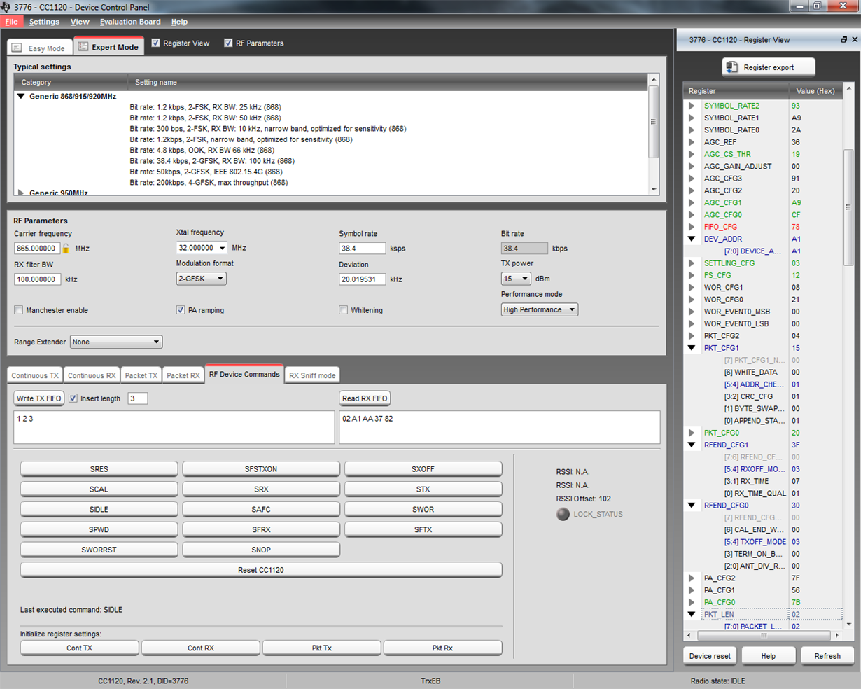
    I did a test with SmartRF Studio where I selected the 38.4 kbps typical setting as a starting point.

    I operated both the transmitter and the receiver from the RF Device commands window.

    The following steps were done:

    TX:

    DEV_ADDR                 = 0xA1

    PKT_CFG1.ADDR_CHECK_CFG  = 0x01

    RFEND_CFG1.RXOFF_MODE    = 0x03

    RFEND_CFG0.TXOFF_MODE    = 0x03

    PKT_LEN.PACKET_LENGTH    = 0x02

    RX:

    RFEND_CFG1.RXOFF_MODE    = 0x02

    RFEND_CFG0.TXOFF_MODE    = 0x03

    Only the transmitter uses address and packet length filtering.

    On the transmitter I write the following packet to the FIFO: 3, 1, 2, 3 on the receiver I use the ack packet 2, a1, aa.

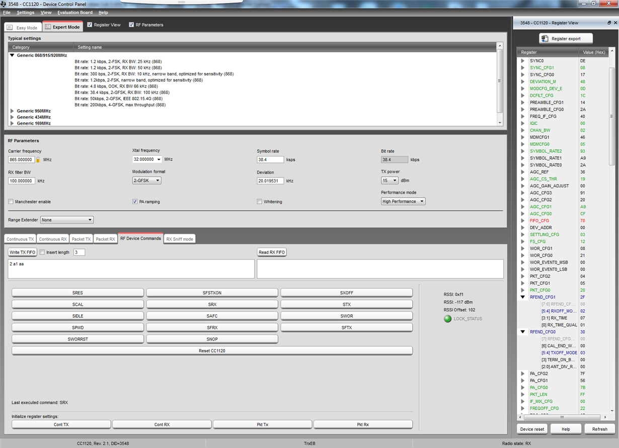
    After writing bot packet to the TX FIFO I strobe SRX on the receiver and STX on the transmitter. I then strobe SIDLE on the transmitter and read the RX FIFO: the result is shown below:

    As you can see the ACK packet is in the FIFO and the 0xaa is the 3rd byte.

     If I do the test over again, but changes the ACK packet on the receiver to 2, a2, aa (wrong address) the transmitter will not receive the ACK packet.

    BR

    Siri