This thread has been locked.

If you have a related question, please click the "Ask a related question" button in the top right corner. The newly created question will be automatically linked to this question.

Sometimes CC1200 goes to SETTLING after successful CCA

Other Parts Discussed in Thread: CC1200

I am seeing a rare case where sometimes CC1200 goes to SETTLING state after doing successful CCA.

In RX mode G0 is configured as PKT_CRC_OK: CC120X_IOCFG0 = 19

In TX mode G0 is configured as PKT_SYNC_RXTX: CC120X_IOCFG0 = 6

G2 is configured as CARRIER_SENSE_VALID: CC120X_IOCFG2 = 16

Here are other important registers:

{CC120X_PKT_CFG2, 0x0C}, // CCA mode: Indicates clear channel when RSSI is below threshold and currently not receiving a packet
{CC120X_RFEND_CFG1, 0x1F}, // radio goes automatically to FSTXON to send ACK message after receiving a good packet
{CC120X_RFEND_CFG0, 0x30}, // radio goes automatically to RX to listen incoming message after sending a packet

I am doing CCA in this way:

error_t m_do_cca() {
uint8_t counter = 0;
uint8_t state = m_get_chip_state();
if (state == CC_STATE_OFF){
return EOFF;
}
else if (state == CC_STATE_CALIBRATE || state == CC_STATE_SETTLING) {
// we can only do CCA in RX mode, so check for that
// if we're idle, calibrating or settling, return ERETRY so the sender will try again
return ERETRY;
}
else if (state == CC_STATE_RXFIFO_OVERFLOW) {
// it is for sanity check
warn4("RXFIFO overflow");
call Spi.strobe(CC120X_SIDLE);
call Spi.strobe(CC120X_SFRX);
#warning radio goes to IDLE after SFRX, who else puts it to RX beside LPL
return FAIL;
}
else if (state == CC_STATE_FSTXON) {
// radio goes automatically to FSTXON to send out ack packet after receive
// that is why we are in this state
}
else if (state != CC_STATE_RX) {
err4("ASSERT wrong state %u", state);
// what if we are in IDLE for some reason, should we switch to RX?
return ERETRY;
}
// carrier sense not yet valid
if (!call G2.get()) {
return ERETRY;
}
call Spi.strobe(CC120X_STX);
while (1) {
state = m_get_chip_state();
counter++;
// check if radio is still in RX
// it means channel is not clear and radio stays in RX
if (counter >= 5 && state == CC_STATE_RX) {
return FAIL;
}
if (state == CC_STATE_TX) {
break;
}
if (counter >= 15) {
return FAIL;
}
}
// just to be sure read out radio state to check if CCA was successful or failed
// 1 - CCA failed, radio stays in RX mode
// 0 - CCA succeeded, radio goes to TX mode
if (!(call Spi.readRegister(CC120X_MARC_STATUS0) & (1<<2))) {
return SUCCESS;
}
else {
// if CCA fails radio stays in RX mode
return FAIL;
}
}

Logic:

  • radio must be in RX state before doing CCA and G2 pin indicating CARRIER_SENSE_VALID must be set
  • if STX is strobed and radio stays in RX, then channel is considered busy and MARC_STATUS0 must have set TXONCCA_FAILED bit
  • if STX is strobed and radio changes state to TX, then MARC_STATUS0 TXONCCA_FAILED bit must be 0


Lets say CCA succeeded, then another function is called that configures G0 pin to PKT_SYNC_RXTX to catch packet sent interrupt. This is TinyOS code hence those "call" keywords.

void m_write_to_txfifo() {
uint8_t* data = (uint8_t*) call ChipconPacket.getHeader(m_tx_msg);
uint8_t length = call ChipconPacket.getPacketLength(m_tx_msg);
uint8_t power = call PacketTransmitPower.isSet(m_tx_msg) ? call PacketTransmitPower.get(m_tx_msg) : m_default_tx_power;

ASSERT(m_tx_msg != NULL);
if (power != m_tx_power) {
m_tx_power = power;
//call Spi.writeRegister(PATABLE, m_tx_power);
}

// set GDO0 to de-assert (falling) if packet is sent.
atomic {
m_waiting_rx_int = FALSE;
call Spi.writeRegister(CC120X_IOCFG0, 0x06);
call G0Interrupt.enableFallingEdge();
}

// TODO, how to put timestamp
// signal HalChipconControl.txStart(call LocalTime.get());

call Spi.burstWriteFifo(data, length);
call CSn.set();
call CSn.clr();
}

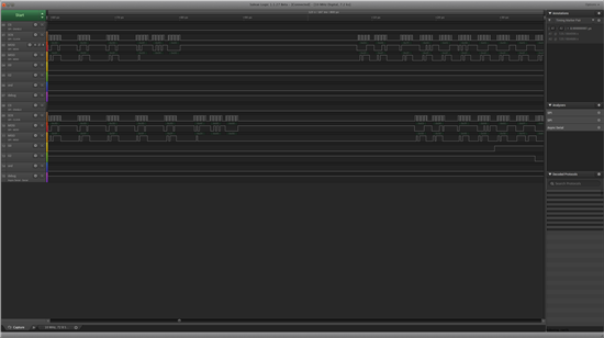
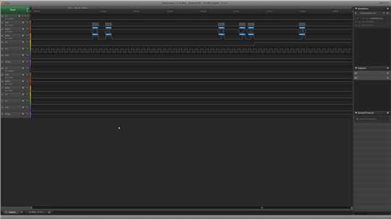
I do not assume that after successful CCA radio goes automatically to SETTLING or to some other state from TX. However this exactly sometimes happening. Fortunately I was able to catch it with logic analyzer. Channels 0-7 are device 1 SPI trace and channels 8-15 are device 2 SPI trace. Notice that these devices are sending almost at the same time. Device 1 start 9 us earlier that device 2.

Look device 2 SPI trace where successful CCA can be seen. However actually if m_write_to_txfifo() is started radio is already in SETTLING state. This is unexpected behavior for me.

Question is if I am doing something wrong in the first place or this is normal and I should try to handle it?

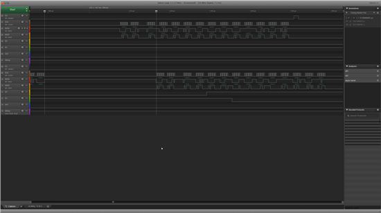
Here is another picture showing strange radio statuses if TXFIFO is filled (being in the wrong state), notice that G2 goes low:


After that radio is in TX_FIFO_ERR state. Firstly radio is put back to IDLE and then FIFO is flushed with SFTX:

The problem is that G2 pin indicating CARRIER_SENSE_VALID never goes high again after this issue therefore cca function does not work anymore. What should I do handle this error correctly?

NB: writing this post I realized that SFTX and SFRX can be called immediately if XX_FIFO_ERR state is detected, I issued SIDLE before those commands maybe this is incorrect?

Andres

  • First of all a comment to the flushing of the FIFOs. The FIFOs should only be flushed in error state or IDLE state. If you strobe IDLE before doing strobing SFTX/SFRX you must poll MARCSTATE and wait for IDLE state to be entered before issuing the strobe command.

    I have never tested CCA with off modes set to something else that IDLE. It might be that the chip behaves differently when changing modes based on off modes compared to what it does when using strobe commands to change modes. Do you have the chance to rewrite your code to use Both TX and RX OFF modes  = IDLE.

    Ifnot, can you make some test code that we can run on our TrxEB that triggers the issue you see so that we can reproduce it here to better understand what is happening and why?

    Sorry that I could not be of any more help at the moment.

    BR

    Siri

  • I would like to use automatic state transitions because they are faster than strobing from IDLE to RX or TX manually.

    Unfortunately I do not have resources to write test application to TrxEB and this case seems to be quite rare. There seems to correlation how busy is the channel. Currently I have little test application on another mote that just generates carrier signal and gradually increases and decreases its output power. This seems to affect how frequently it is happening, however I am still testing it.

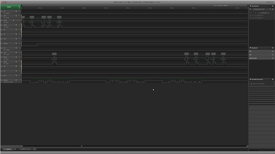
    I added new screenshots that now show very bizarre activity on G2 pin (CARRIER_SENSE_VALID). It happens during writing to TX FIFO, notice that radio starts sending very strange status bytes.

    G0 is configured as PKT_SYNC_RXTX, after some time I got interrupt from G0 that is considered to be sendDone event.

    Here radio status is read out and it is TX_FIFO_ERROR, it is cleared with SFTX however G2 does not change, so there must be something else completely wrong. Here is the trace:

    I think I am going to try to handle it with chip reset if TX_FIFO_ERROR is happening.

    Here is register configuration that is read in on init:

    // 40 MHz crystal
    #if CHIPCON_DATA_RATE == 10000000UL
    // RX filterbandwidth: 1666.6666 kHz
    // Modulation: 4GFSK
    // Deviation: 400 kHz
    // Datarate: 1000 kbps
    #define _DEVIATION_M 0x47
    #define _MODCFG_DEV_E 0x2F
    #define _SYNC_CFG1 0xA8
    #define _CHAN_BW 0x01
    #define _SYMBOL_RATE2 0xC9
    #define _SYMBOL_RATE1 0x99
    #define _SYMBOL_RATE0 0x99

    #else
    #error "Unsupported data rate"
    #endif


    #define BAUD_RATE CHIPCON_DATA_RATE


    // frequency presets for 40 MHz crystal
    #if CHIPCON_FREQUENCY == 869525
    #define _FREQ2 0x56
    #define _FREQ1 0xF3
    #define _FREQ0 0xD7
    #else
    #error "Unsupported frequency"
    #endif


    static const register_setting_t cc120x_settings[]= {
    {CC120X_IOCFG0, 19}, // RX: 0x13 assert if packet with correct CRC is received, deassert when going to RX mode
    // TX: 0x06 assert when sync is sent out, deassert at the end of packet
    {CC120X_IOCFG2, 16}, // CARRIER_SENSE valid

    {CC120X_DEVIATION_M, _DEVIATION_M},
    {CC120X_MODCFG_DEV_E, _MODCFG_DEV_E},
    {CC120X_SYNC_CFG1, _SYNC_CFG1},
    {CC120X_DCFILT_CFG, 0x1E},
    {CC120X_PREAMBLE_CFG0, 0x8A},
    {CC120X_IQIC, 0x80},
    {CC120X_CHAN_BW, _CHAN_BW},
    {CC120X_MDMCFG1, 0x42},
    {CC120X_MDMCFG0, 0x01},
    {CC120X_SYMBOL_RATE2, _SYMBOL_RATE2},
    {CC120X_SYMBOL_RATE1, _SYMBOL_RATE1},
    {CC120X_SYMBOL_RATE0, _SYMBOL_RATE0},
    {CC120X_AGC_REF, 0x2F},
    {CC120X_AGC_CFG1, 0x12},
    {CC120X_AGC_CFG0, 0x84},
    {CC120X_AGC_GAIN_ADJUST, RSSI_OFFSET_2_COMPLEMENT}, // take RSSI offset into account
    {CC120X_AGC_CS_THR, 0xED}, // -100 (2 complement number in dB)
    {CC120X_FIFO_CFG, 0x00},
    {CC120X_FS_CFG, 0x12},
    {CC120X_PKT_CFG2, 0x0C}, // CCA mode: Indicates clear channel when RSSI is below threshold and currently not receiving a packet
    {CC120X_PKT_CFG1, 0x43}, // data whitening
    {CC120X_PKT_CFG0, 0x20}, // variable packet length mode. Packet length configured by the first byte received after sync word.
    {CC120X_RFEND_CFG1, 0x1F}, // radio goes automatically to FSTXON to send ACK message after receiving a good packet
    {CC120X_RFEND_CFG0, 0x30}, // radio goes automatically to RX to listen incoming message after sending a packet
    {CC120X_PA_CFG1, 0x7F}, // output power
    {CC120X_PKT_LEN, 0x6E}, // max packet length 110
    {CC120X_IF_MIX_CFG, 0x00},
    {CC120X_FREQOFF_CFG, 0x23},
    {CC120X_MDMCFG2, 0x00},
    {CC120X_FREQ2, _FREQ2},
    {CC120X_FREQ1, _FREQ1},
    {CC120X_FREQ0, _FREQ0},
    {CC120X_FS_DIG1, 0x04},
    {CC120X_FS_DIG0, 0xA3},
    {CC120X_FS_CAL1, 0x40},
    {CC120X_FS_CAL0, 0x0E},
    {CC120X_FS_DIVTWO, 0x03},
    {CC120X_FS_DSM0, 0x33},
    {CC120X_FS_DVC1, 0x7F},
    {CC120X_FS_DVC0, 0x0F},
    {CC120X_FS_PFD, 0x00},
    {CC120X_FS_PRE, 0x6E},
    {CC120X_FS_REG_DIV_CML, 0x1C},
    {CC120X_FS_SPARE, 0xAC},
    {CC120X_FS_VCO0, 0xB5},
    {CC120X_XOSC5, 0x0E},
    {CC120X_XOSC1, 0x03},
    };

    Andres

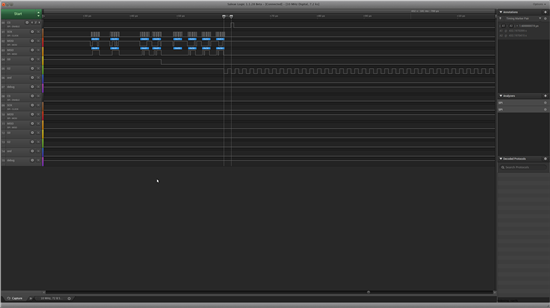
  • I got some more information. If this is happening radio starts to generate something continuously:

    Andres

  • Hi

    I have looked at the plot from the logic analyzer and there are several things that do not make sense.

    When you are strobing STX the radio reports that it is in FSTXON state and still you strobe STX (when using CCA STX should only be strobed from RX).

    When you write to the IOCFG0 register the radio reports TX but the next write (burst write to TX FIFO), the radio reports IDLE and then SETTLING.

    I suspect that the SPI is not meeting the requirements in the user guide, so even if what you send to the radio looks correct when interpreted by the logic analyzer, the radio interpret the data/commands differently, hence the strange behavior.

    The main reason for thinking this is the signal you see on GPIO2. This is a square wave with a frequency of 1/1.6 us = 625 kHz, which is 40 MHz/64. The only thing this signal could be is the EXT_CLOCK signal with ECG_CFG.EXT_CLOCK_FREQ = 0 (divide by 64).

    The way to configure GPIO2 to output this signal is to write 0x31 to 0x01:

    00000001, 00110001 (address, data)

    According to the logic analyzer you are writing 0x02, 0x02, 0xE3 to the TX FIFO using burst access.

    Looking on the two last bytes (0x02, 0xE3) in binary they look like this:

    00000010, 11100011

    If we assume that there are some timing issues so that the SPI spec is not met, the radio might interpret this as

    000000010, 011100011 (0x01, 0x71)

    This will output the inverted EXT_CLOCK on GPIO2 and hence explain what you are seeing.

    I will strongly recommend that you monitor your SPI traffic with a scope to see that the SPI spec. is not violated.

    An easy test you also can do is to write 0x02, 0xE3 over and over again in IDLE mode to see if the radio interpret this as setting GPIO1 to LOCK or setting GPIO2 to EXT_CLOCK.

    BR

    Siri

  • >>>When you are strobing STX the radio reports that it is in FSTXON state and still you strobe STX (when using CCA STX should only be strobed from RX).

    I did not know that. I wanted to achieve very quick state transition from RX to TX to send out ACK packet after receiving data (not every packet is ACKed, so sometimes radio is commanded to go back to RX from FSTXON). Radio is configured to go automatically to FSTXON state after receive (yes CCA is configured) and STX is strobed to send out ACK packet.

    Lets say I do not use CCA, in this case after mentioned logic is correct? 

    To achieve the same logic using CCA I should:

    1. disable CCA, wait for packet

    2. if packet is received radio still goes automatically to FSTXON state however this time it is okay because CCA is disabled

    3. ACK is sent out without CCA

    4. If normal data is sent out and we are in RX mode enable CCA and try to go to TX state if it succeeds fill TXFIFO and send packet out, if it fails disable CCA (otherwise we would receive a packet and still got to FSTXON with CCA enabled.)

    Could you comment if this is reasonable.

    PS: I cannot find this FSTXON and CCA conflict from user guide, could you point me out if there is any information about that. 

    PS2: Actually my current method using CCA seems to work quite nicely except those error conditions that might be related to SPI timings, is this sheer luck or is undefined behavior this time on my side?

    Andres

  • CCA is used because you want to know is the channel is clear before sending a packet. To know if the channel is clear or not, the radio must be in RX to “listen” on that channel. This is clearly stated in the user guide: “When an STX or SFSTXON command strobe is given while CC120X is in the RX state, the TX or FSTXON state is only entered if the clear channel requirements are fulfilled”.

    If you want to use CCA you can either set RXOFF_MODE = IDLE.

    When a packet is received, you strobe SRX again, wait for CS_VALID is asserted and then strobe STX.

    If you want to speed up the process you set RXOFF_MODE = RX, you wait for a packet to be received, you wait for CS_VALID to be asserted, and you strobe STX.

    However, I think you need to follow up on what I suggested in my last post. If you suddenly get EXT_CLOCK out on a GPIO pin without configuring this pin through your SW, there must be something with your SPI interface that is not according to spec. Maybe it works most of the times but sometimes it fails.

    I cannot understand you comment about CCA working nicely. If you are not in RX and CS_VALID is not asserted when you strobe STX, the packet will be sent regardless of other traffic on the air.

    Siri

  • I would like to clarify one more thing. Lets say CCA is enabled and radio is going automatically to FSTXON state after receive. 

    As you mentioned:

    “When an STX or SFSTXON command strobe is given while CC120X is in the RX state, the TX or FSTXON state is only entered if the clear channel requirements are fulfilled”.

    What really happens in automatic mode? Is it doing CCA automatically if doing state transition to FSTXON after receive? If it is so then in which state it is going if channel is busy?

    I just would like to get better understanding about CC1200 capabilities.

    In my last comment about CCA working nicely I meant that It seemed to me that after receiving a packet radio goes to FSTXON without doing CCA and if then STX is strobed it goes to TX mode and ACK is sent out without checking channel (for ACK it is expected behavior), however if normal packet is sent out of course radio must be in RX before doing CCA. So I just wanted to get confirmation that doing it this way is also okay.

    Andres

  • CCA does only work when you are in RX and you manually strobe STX or SFTXON. If you enter these states based on OFF_MODES the channel will not be checked.

    Siri