This thread has been locked.

If you have a related question, please click the "Ask a related question" button in the top right corner. The newly created question will be automatically linked to this question.

New CC1200 design can't send or receive packet to/from the TI EVM with the CC1200 module.

Other Parts Discussed in Thread: CC1200

We've built a new hardware platform that implements the CC1200 reference design for the 868mhz module.  I've ported the portion of the TI Evaluation platform code that did the RX Sniffer packet transmit and receive.  For some reason, when I run my code on our board, we see a spike in our frequency spectrum analyzer centered at 868mhz that looks identical to the TI Evaluation module when it tries to transmit, but no data ever appears on the receiving TI Evaluation board running the "Slave" portion of the RX Sniffer test.  When I run my code on the TI Eval board, the packets appear at the "Slave" without issue.  I'm convinced the code has been ported properly since the same code running on the TI Board appears to work fine, yet when run on our new hardware, no packets...


I'm looking for some assistance in how to go about debugging this issue.  From everything we have been able to look at, it appears that the new hardware is transmitting a packet, but for some reason the TI Board isn't recognizing it.  Is there some additional board calibration required that I may be missing?  I know there was mention in the User's guide and the code that some RSSI Offset needs to be calibrated or measured in order to get real RSSI numbers.  But I can't see how that would be causing the issue.


Any help would be greatly appreciated.

  • Hi
    The RSSI offset has nothing to do with this. I would strongly recommend that you test SW and HW separately and also that you try different combination of HW.
    Start by running your SW on TI HW (EMs) to make sure that your SW is OK.
    Then try to use our HW as receiver while transmitting with your HW. If this does not work, you know that you have problems in TX. Then try to use our HW as transmitter and your HW as receiver. If this does not work, you also have an RX problem.
    You can also do a test where you use your HW both as receiver and transmitter. If this work, your problem might be that your frequency is offset compared to on TI’s HW. Do you have a spectrum analyzer so that you can check your carrier to see if it is where it is supposed to?
    Siri
  • Hello Siri,
    Thank you for your reply. The debug procedure you describe is essentially what I have done here. I'm sorry if my initial post was not clear. I have successfully run my code on the TI eval platform to sent packets from one TI board to the other. However when I run my code on our hardware, the TI platform does not receive the packets my hardware transmits. We have checked the signal with a spectrum analyzer as you suggested, and we don't see any obvious difference between the packet transmission from our board or the TI board. Both generate a pulse of about the same shape and magnitude centered at 868mhz. So I am at a loss as to what to try next. Is there any signal I could route to the Gpio pins that may help diagnose the problem? Any other suggestions you might have would be greatly appreciated.
    Thanks again.
    Chris
  • - Which datarate/ deviation/ modulation/ RX BW do you use?
    - Could you post the spectrum from the signal you send with the TI EVM (receive successful) and your hardware (receive not successful) with the spectrum set to use low RBW and low span to see the details.
  • Hello,

    I am not entirely sure how to answer your question concerning data rate / deviation etc. other than to say I copied the register configuration parameters that were being used for the RX Sniffer portion of the test software included with the TI eval platform. I was trying to minimize changes in my code that would possibly introduce problems. So, I haven't used the rf studio app to generate new settings. I'm using the settings in the test application. Hopefully that answers your first question. For the second part, I will need to get access to the spectrum analyzer again and capture the info you've requested.
  • Hello,

    We would like to make sure we capture the spectrum analyzer images that would be useful.  You mentioned low RBW and low span.  Can you be more specific of exactly what values you'd like for these settings?

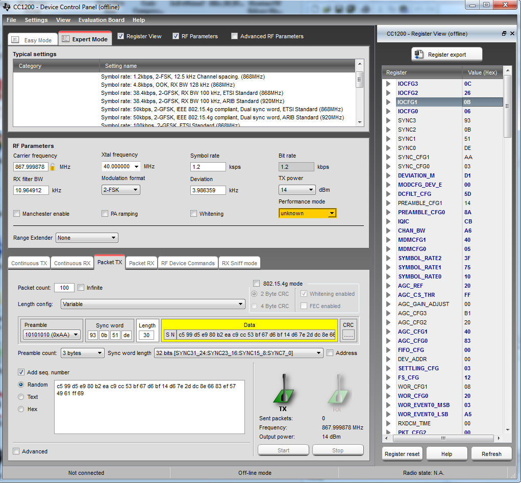
    Also, I took the time to enter all the register values from the code into RF Studio in the hopes that it would show the datarate/ deviation/ modulation/ RX BW information you requested.  Here's the pertinent information.  The values entered were directly from the "simpleLinkTestSniffCC120x" structure in the cc120x_sniff_mode_api.c module in the per_test example application.  Here's what the RF Studio displayed after entering the values:

    Carrier Frequency:  867.999878MHz

    Xtal Frequency:  40.000000MHz

    Symbol Rate:  1.2 ksps  

    Bit Rate:  1.2kbps

    RX Filter BW:  10.964912khz

    Modulation Format: 2-FSK

    Deviation:  3.986359khz

    TX Power:  14 dBm


    Attached is a screenshot of the RFStudio screen.  I believe the RF Parameters section of the screen is what you were interested in:

    Again, any help you can send our way will be greatly appreciated,

    Chris.

  • Have you tried if you get communication with 25 kHz RX BW? The classical issue here is a small frequency offset between Rx and Tx
  • Hello,

    I have not tried the 25kHz RX BW yet. However, while I RF Studio fired up, I tried to generate a couple more configurations to try. I went to the Expert Mode tab and selected the "Symbol rate: 1.2bps, 2-FSK, 12.5 kHz Channel Spacing (868MHz)" configuration. By default that one had the 10.964912kHz RX Filter BW setting. I exported the registers and loaded those values in my code. Again, the code worked on the TI platforms, but not on my hardware. So, I decided to try the "Symbol rate: 4.8kbps, OOK, RX BW 128kHz (868MHz)" configuration. Once again, I exported the registers and loaded them into my code. These settings worked on both the TI Platform as well as my hardware. Does this narrow down where the problem might be? Several things changed in the configurations (Modulation, Symbol rate, RX filter BW, etc.). I'll have to try the larger RX filter BW value in my first configuration using the 2-FSK modulation to see if that works too.

    If this is actually a problem that is solved with a change in the RX filter BW value, is that indicative of a particular problem in my hardware / PCB Layout of the circuit?

    Thanks for your help so far,
    Chris
  • Hello,

    I just tried changing the Rx Filter BW in the "Symbol rate 1.2kbsp, 2-FSK, 12.5kHz Channel Spacing( (868MHz)" configuration and it did not work. My board still cannot talk to the TI Eval board although the two TI Boards can still exchange packets. So it looks like the ASK/OOK modulation works between my board and the TI Boards, but the 2-FSK modulation does not.

    What might be causing this?

    Thanks in advance,
    Chris.
  • Have you checked the frequency offset between the two boards?

  • When you are aking for the frequency offset, do you mean the offset from the 868mhz?  Or is there some other offset you'd like me to measure?

  • The frequency offset between the two units that try to communicate.
  • Hello,

    We finally got access to the frequency spectrum analyzer again and set the RBW and span low enough so we could see that the two boards were in fact offset by about 15khz.  So using your previous suggestion about increasing the size of the RX BW, I set it to 30khz and then things magically started working.

    So, thanks for your help!

    Is it normal to see that much offset in the boards?  Is it simply the accuracy of the 40mhz crystal that determines the offset or is there something else in the circuit that would be responsible for it.  I'm trying to anticipate we components we may need to tighten specs on when we go into production.


    Thanks again for your help.

    Chris.

  • 15 kHz offset between the boards is too much. You can easily calculate the expected maximum variation for the xtal by looking in the datasheet and figure out the ppm variation.

    The frequency will also shift as a function of the crystal load caps. Ensure that the load caps are equal on both boards.