This thread has been locked.

If you have a related question, please click the "Ask a related question" button in the top right corner. The newly created question will be automatically linked to this question.

CC1101+CC1190 product, spectrum noise: What kind of noise is that? Where could it come from?

Other Parts Discussed in Thread: CC1101, CC1190

Dear all,

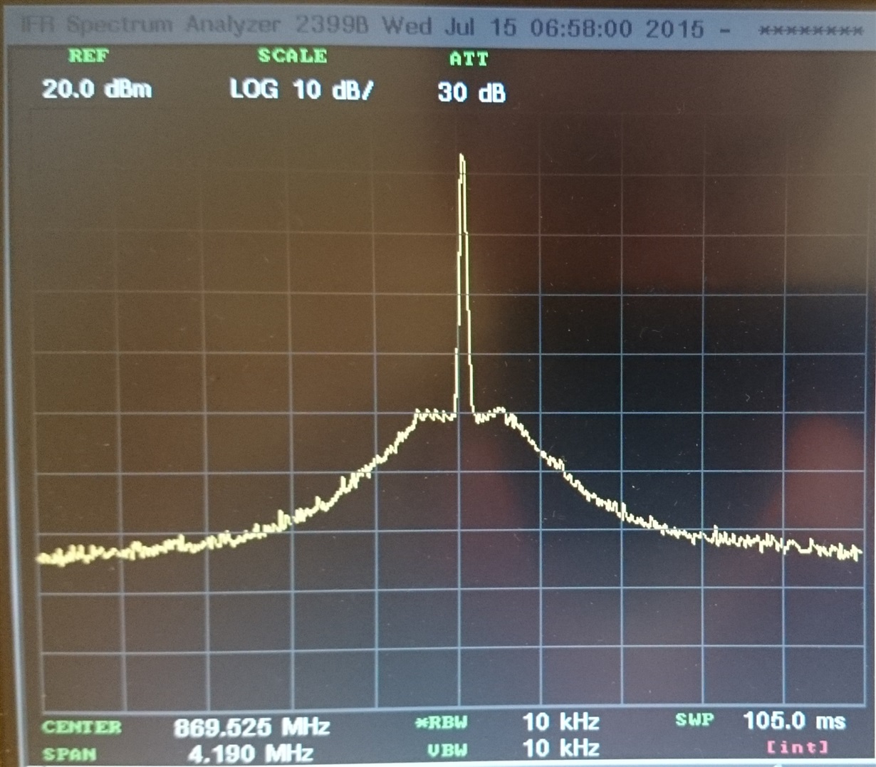
I am struggling with the CC1101 PA TABLE configuration in order to lower some noise visible in this spectrum view.
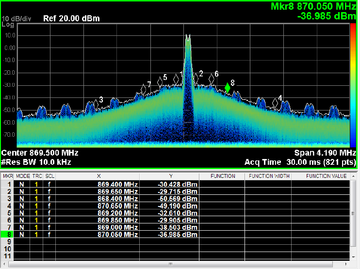
As you can see, the modulation bandwidth seems to be mirrored at each ~300kHz. I had a look at the VCC rail, it is very clean (behind a LDO). I thought it was the ON/OFF transient  of the cc1101/cc1190, I tried many different PATABLE configurations, and finally I kept on that one:


0x00    //-59.3 dBm on CC1101
0x03    //-30.2 dBm on CC1101
0x0F    //-20.0 dBm on CC1101
0x1E    //-15.1 dBm on CC1101
0x25    //-12.5 dBm on CC1101
0x36    //-8.1  dBm on CC1101
0x37       //-6.9  dBm on CC1101
 0x37      //-6.9  dBm on CC1101

The PATABLE configuration itself does not seem to have any influence on the out-of-channel transient energy shown in this figure above.

Then, who knows where can this kind of intermodulation noise come from?

Thanks you.

  • - First, try sending a CW, see if the 300 kHz signal is there,
    - Then, send a continuous modelated signal, the same as above

    When sending packets you will get a sinc function in the spectrum (a square wave). Note that ETSI does not require you to test sending packets.
  • Hi TER,

    Thank you for the answer.

    I made a new measure of an unmodulated CW:

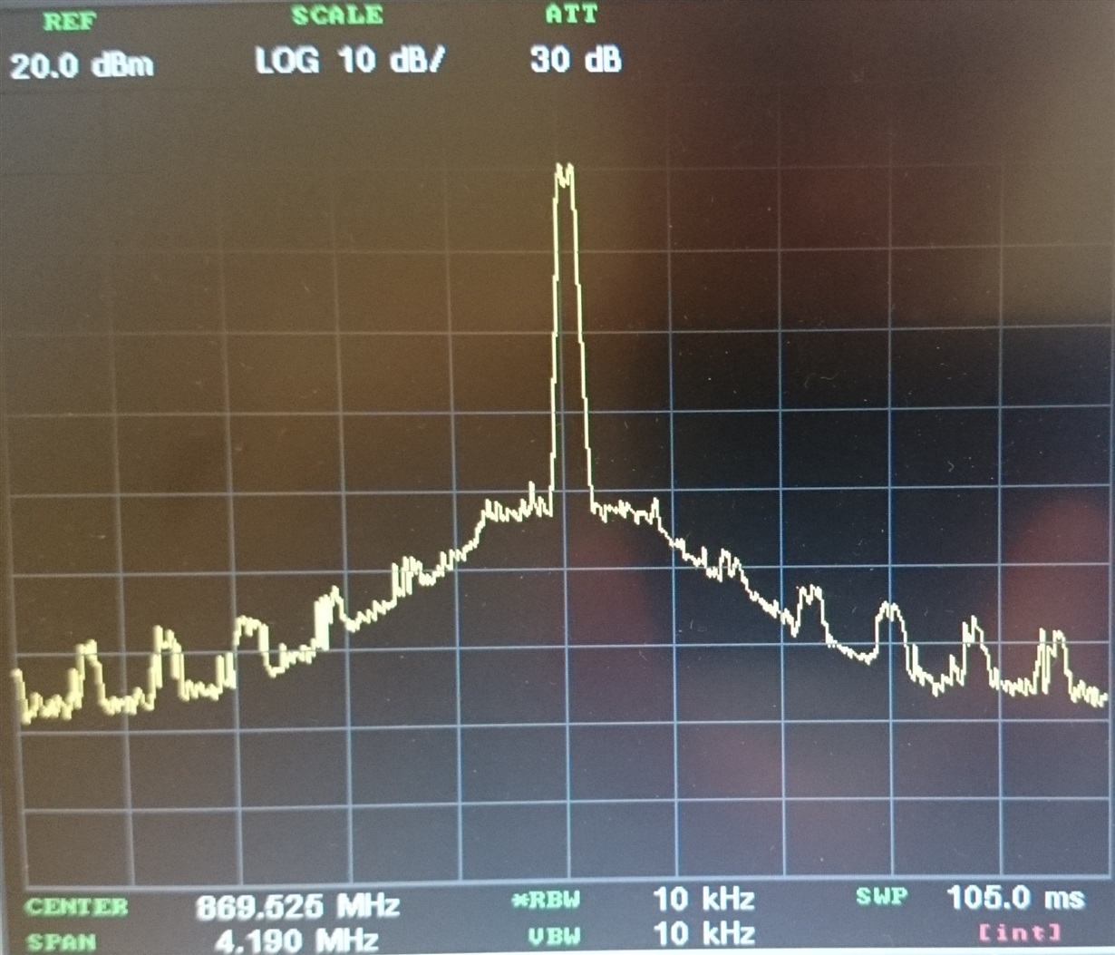
    The response seems OK, no out-of-band noise at all. Thus, my problem seems to come from the radio switching from RX to TX... In order to compare, I made the same measure but now with packet TX:

    Any idea from that 300kHz?


    Does anyone know if there is a specific PATABLE configuration to use when CC1101 is coupled with a CC1190? (@869MHz, TXpower_Max=20 [dBm] , Baud=38400bits/sec)

  • OK, so not anything fundamentally wrong, what you see is the transitions from not output power to max when sending packets.

    But: Why are you looking into this? The regulations do not require you to test compliance by sending packets? (see  for some details.)

  • Thank you so much TER.

    I don't fully understand the step1 and step2 methods stated at EN300-220-1 V2.3.1 7.5.3, but I read somewhere that the transient power should be measured with a "quasi peak detector+ Lowpass filter", in order to average the transient among a certain period of time. The figures above were generated using a "positive peak detector" which seem to be another method, with theoretically different results in term of magnitude of the spectrum. I will have soon the opportunity to measure my system with a real "quasi peak detector" method, I will probably see something better in term of transient power.
    Anyway, thank you TER for your support.
  • The standard specify quasi peak detector. The transient power limit is fairly relaxed and if you follow step1 and step2 carefully you should have no problem passing.
  • TER,

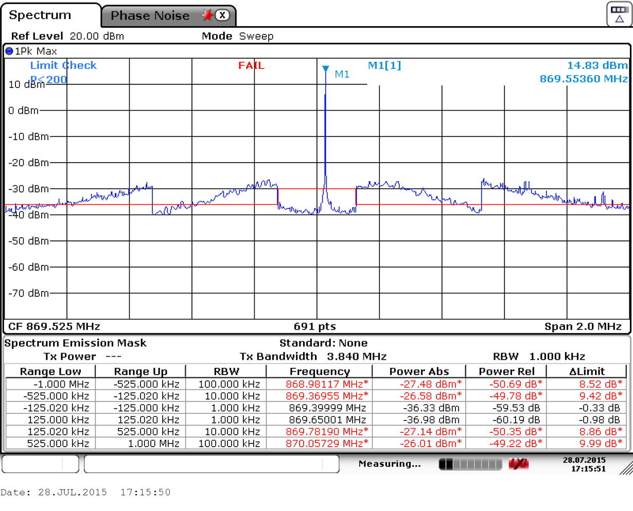
    I carried out a measurement , as for the Modulation Bandwidth (EN 300 220 - 1 , 7.7) , to compare with the Figure 4.18 in the AN094 from TI, except I did not modulate packets, only a CW. Here is my result:

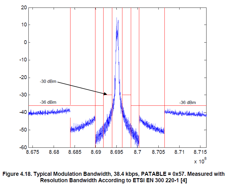
    And to compare, here is the figure 4.18 from the Application Note AN094:

    I really do not understand how TI carried out this measurement. Even in unmodulated continuous carrier wave mode, with 15dBm output, my system was far to pass the compliance.

    I think it may come from the CC1101 PLL noise. What is your opinion about that?

    Could you please give us any further information about the setup and configuration used to proceed to measurement of Figure 4.18?

    Thank you.

  • Please check your setup again. 

    fe (sub band edge) will in this case be +/-125 kHz.

    From fe to fe + 200 kHz the limit is -30 dBm measured with 1 kHz RBW

    fe + 200 kHz to fe + 400 kHz the limit is -36 dBm measured with 1 kHz RBW

    fe + 400 kHz to fe + 1 MHz the limit is -36 dBm measured with 10 kHz RBW

    fe + 1 MHz and above the limit is -36 dBm measured with 100 kHz RBW

    It looks like you have used a too large RBW on all tests. 

  • Thank you TER, my RBW was not correctly settled. Now That's OK for the Modulation Bandwidth (7.7).

    But I really don't understand some points on Step 1 and Step 2 of the Transient poser (7.5). I did not find any information about that in the AN094 : "Using the CC1190 Front End with CC1101 under EN 300 220", as the Transient power in not covered in this document (why?!?? ).

    From what I understand in clause 7.5 "Transient power", this following methodology should be true (please correct me if I'm wrong):

    - The Transient power measurement can be carried out with a spectrum analyzer, if it employs a quasi-peak detector.

    - In order to go through Step 1 with a spectrum analyzer, the Transient power must be measured in ZERO SPAN mode,in respect with those conditions:

    a) Trace acquired through a quasi-peak detector

    b) RBW=120kHz, Sweep time greater or equal than 60sec (for a EUT sending 5 packets of 1 second duration within 1 minute)

    c) Acquire the Transient power level at typical frequencies specified by the limit values for the Modulation bandwidth(7.7, figure 7)

    - If Step 1 fails, proceed to Step 2:

    a) Repeat the procedure but with the EUT set to transmit continuously.

    b) Repeat measurement each 120KHz both upwards and downwards of the carrier, starting at (Fa+100KHz) and (Fb-100KHz) (Fa(=upper freq) and Fb(=lower freq) determined in the Modulation Bandwidth(7.7) measurement).

    c) if each measurement in Step 1 is no more than 3dB greater than the respective measurement in Step 2, the Transient power test is "PASS", otherwise it FAILS.

    According to this procedure, I have a few questions:

    - Which kind of acquisition have to be settled? Average, max-hold, write-clear?

    - VBW is not specified. Is it still fixed with the following formula: VBW >= (3*RBW) ?

    - What did I forget to mention when proceeding to Step 1 and Step 2?

    I know there is a lot of points to answer to, but I am convinced that this procedure will be useful to refer at in the future.