This thread has been locked.

If you have a related question, please click the "Ask a related question" button in the top right corner. The newly created question will be automatically linked to this question.

CC2541 ADC inaccuracy sampling

Other Parts Discussed in Thread: CC2541, CC2530

Hello,

I am using CC2541 to sample and transmit ECG signals. But the result shows there is something wrong with the ADC sampling. 

I try to input a 1Hz sin signal to P0_0, and the code is based on "SimpleBLEPeripheral". Reference voltage is AVDD(3.3V). The period sampling task is called every 5ms. The sampling code is as following:

reading=HalAdcRead(0,HAL_ADC_RESOLUTION_14);
ECGData1[counter] = ( reading >> 8);
ECGData1[counter+1] = (reading & 0xff);

When there are 20 samples, the data is transmitted to the Smartphone.

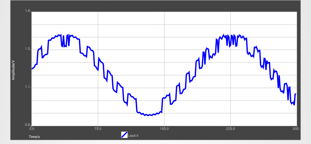
But on the smartphone, the received signal is as the following figure.  But if I input a static voltage or decrease the amplitude of sin signal to below 40mV, the result is right. I can not find out the reason for this result. Can anyone help me?

  • And I also use CC2530 to sample the same signal. The schematic, sampling frequency and reference voltage are all the same. But the result on CC2530 shows right. On the datasheet, the ADC in CC2530 and CC2541 have the same characteristic. But why the have different result?
  • Hi Yishan,

    The ADC in the two devices is the same except for a slightly different internal reference.
    In your case you have higher input voltage than the internal reference so I assume you have either an external reference or VDD/3?

    Are you running the BLE stack on CC2541 or more or less the same software as well? Have you measured the signal input with an oscilloscope to verify the input signal is OK? It looks to me that there is some noise coupling going on here (perhaps ground bounce) as you see the sine wave in both cases but shifted up/down with a DC component.

    Regards,
    Svend
  • Hi Svend,
    Thank you for your reply. I define my reference voltage to external AVDD (HAL_ADC_REF_AVDD) for both CC2541 and CC2530. And I am running the BLE stack on CC2541.
    The input signal has no problem. I have checked on the oscilloscope. I do not think it is from the noise. Because the sin signal from a signal generator is directly connected to the input of ADC. I also input a static voltage and sin signal with 40mV amplitude. The results shows very good.
  • Hi Yishan,

    Using the BLE stack with software triggering of the ADC will cause non-deterministic sample points as the BLE stack will run with higher priority.
    You should consider doing periodic sampling with a timer and DMA for accurate sampling.

    Regards,
    Svend
  • Hi Svend,
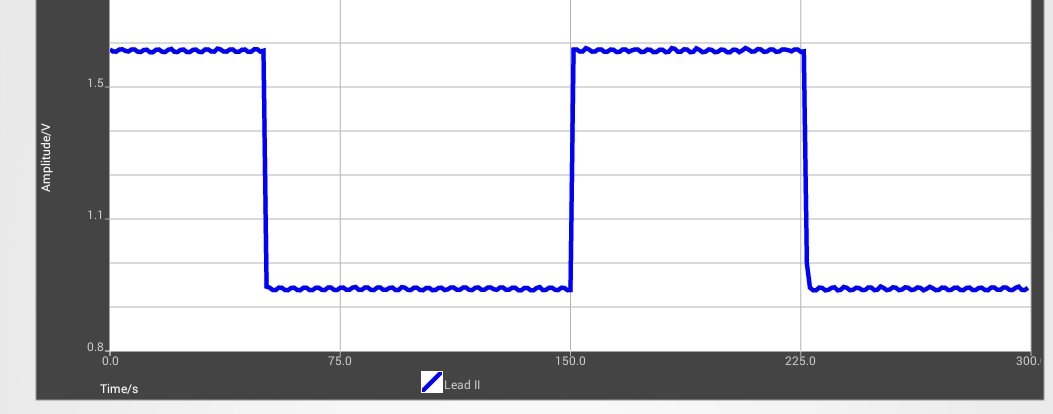
    I try to do sampling in Timer1. But the result is the same. And I find that if I input a square signal. The result is right. So it means that, the ADC can only sample the signal with low variation. But I still con not find the reason for that.
  • Yishan,

    What are you using as the source for the ADC? Do you have sufficiently low enough source impedance to drive the ADC input?
    It should be more or less the same ADC in there but some of the CC25XX devices sample at 4.67Mhz internally instead of 4Mhz which would lower the input impedance.

    Regards,
    Svend
  • Hi, Svend,

    Thank you for your reply.

    The input of the ADC is directly from the Agilent waveform generator. If it is the impedance's problem, only the amplitude will be effected. But right now the amplitude is right, and the square signal does not has this problem. The following figure is the received data in smartphone, when a square signal is inputted to ADC.


    Regards,

    Yishan

  • Vincent,

    Have you tested multiple devices to rule out any issues with this specific device?
    I cannot think of any internal reasons that would cause this. It would be interesting if you could also log the data to RAM and read out to ensure nothing goes wrong during the transfer over-the-air or on the phone side.

    .:svend
  • It could look like the least significant byte of each sample has been treated as signed, not unsigned. If you then calculate each sample as ECGData1[counter] * 256 + ECGData1[counter + 1], I believe that would explain the behavior, and also the fact that a small signal behaves well. As Svend says, you should try looking directly at the data in RAM.
  • Yes, you are right. I find the reason for this problem. Thank you very much.