This thread has been locked.

If you have a related question, please click the "Ask a related question" button in the top right corner. The newly created question will be automatically linked to this question.

Bluetooth Pairing Using Wireless Heart Monitor BLE Reference Design

Other Parts Discussed in Thread: ADS1293, CC2541, CC2540, TIDA-00096, CC-DEBUGGER

Hello,

We have the board from the wireless reference design TIDA-00096 which we're using to test the CC2541 and ADS1293. I have the heartrate example taken from the reference successfully loaded onto the board via IAR workbench (latest version). I'm trying to pair the board with a receiver bluetooth on a USB dongle (not the CC2540 USB kit) and to display the data using our own custom PC software. However, the device is not showing up on bluetooth discovery. How can I test the board & firmware to ensure that it's running properly with respect to the reference source code? I measured 0V on RF_P and RF_N. I want to verify the board is functional for now. Any help would be appreciated! 

  • You could prototype / test using a CC2540 USB dongle and BTool.
  • Thank you for your reply, Tim. I received a CC2540 dongle and downloaded the Packet Sniffer and BTool. I have power applied to the wireless board and the USB dongle is connected to the PC. However the BTool is not recognizing the COM port for the dongle (prompted with Error Writing to COM). I'm receiving this on the Packet Sniffer with the CC2540 dongle selected. I'm trying to verify the board is properly configured and want to send/receive any data as a test. Can you advise on how to proceed? I'd appreciate it, thank you.    packet sniffer ble.psd

  • Hussam,

    The default firmware on the dongle is for the packet sniffer only. If you need to use BTool with it you need to re-flash it with the HostTest firmware using CC-DEBUGGER . The hex file to use with BTool comes with the BLE stack and is found at <ble_install_path>\Accessories\HexFiles\CC2540_USBdongle_HostTestRelease_All.hex.

    Regards,
    Svend
  • Thank you for the reply!

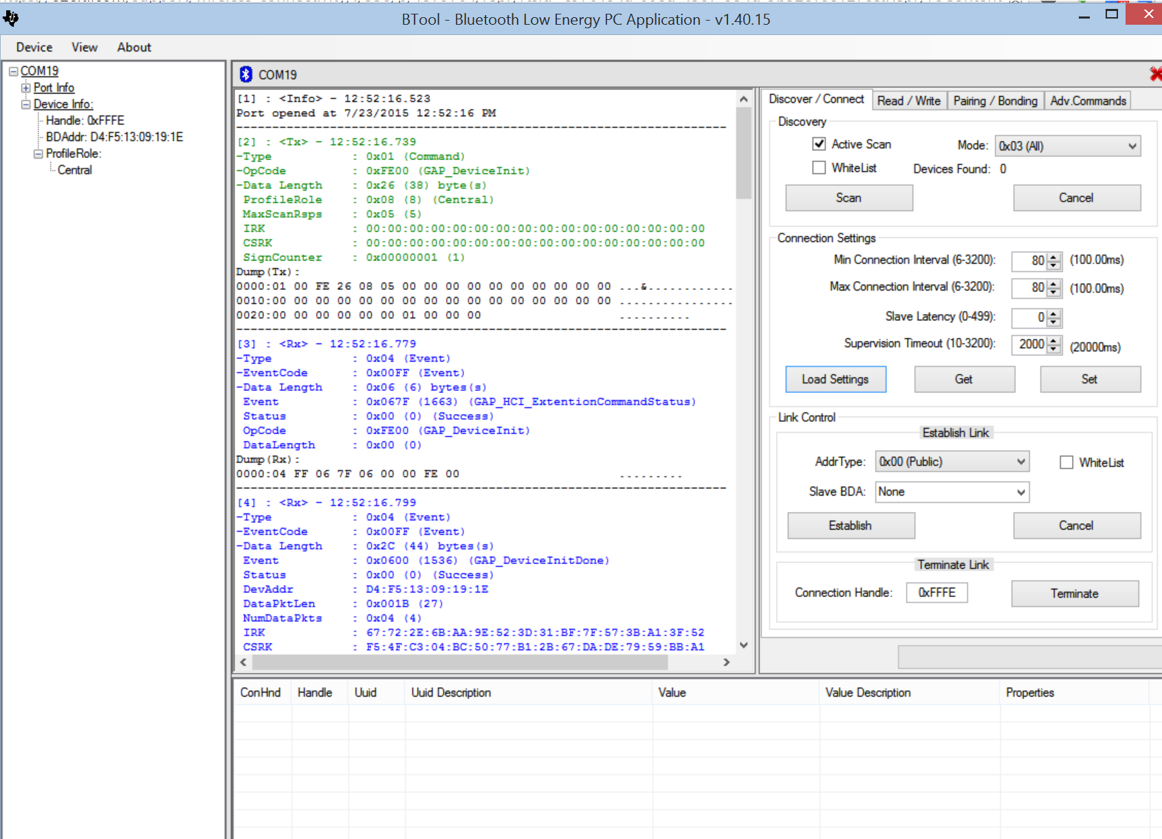
    I re-flashed the dongle with the hex file and the device shows up as TI CC2540 USB CDC Serial Port in Device Manager. I'm now using the BTool, searching for devices and it's returning 0 in the active scan. What else can I test for with the wireless board and the usb dongle? It looks like the transceiver on the cc2541 is not active. Thanks for any advice. 

  • Hello,

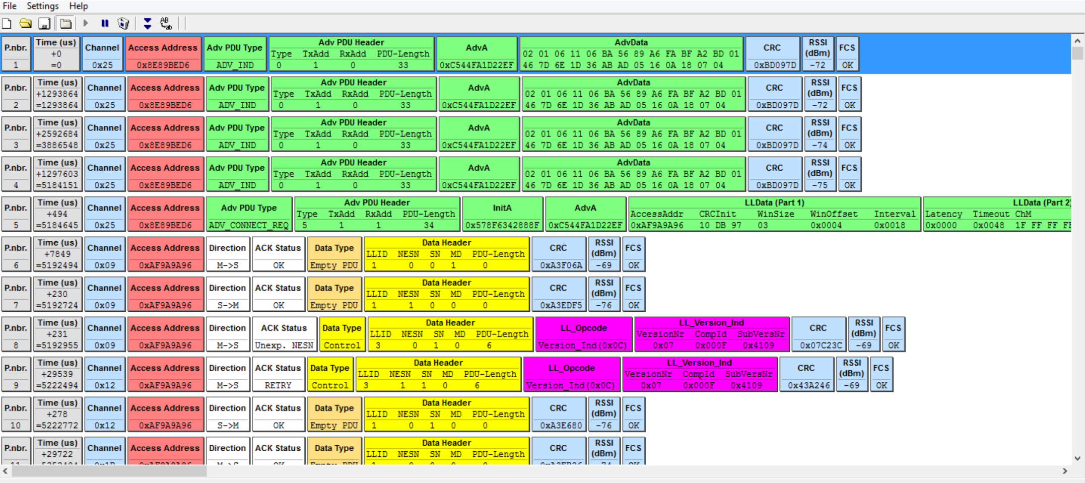
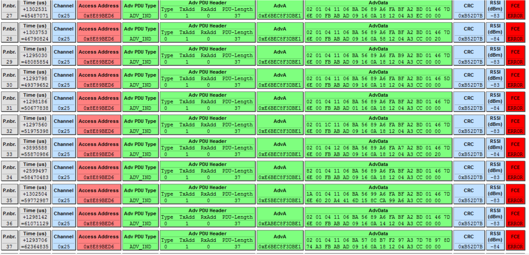
    I figured out how to recognize the device through BTool and I can see the board through an iPhone app, but I'm unclear how to initialize/setup so that I receive the channel data. What else needs to be done in BTool? Are there specific commands? We've written a PC app following the data format outlined in the wireless reference user guide, but I'm receiving the following using the Packet Sniffer: 


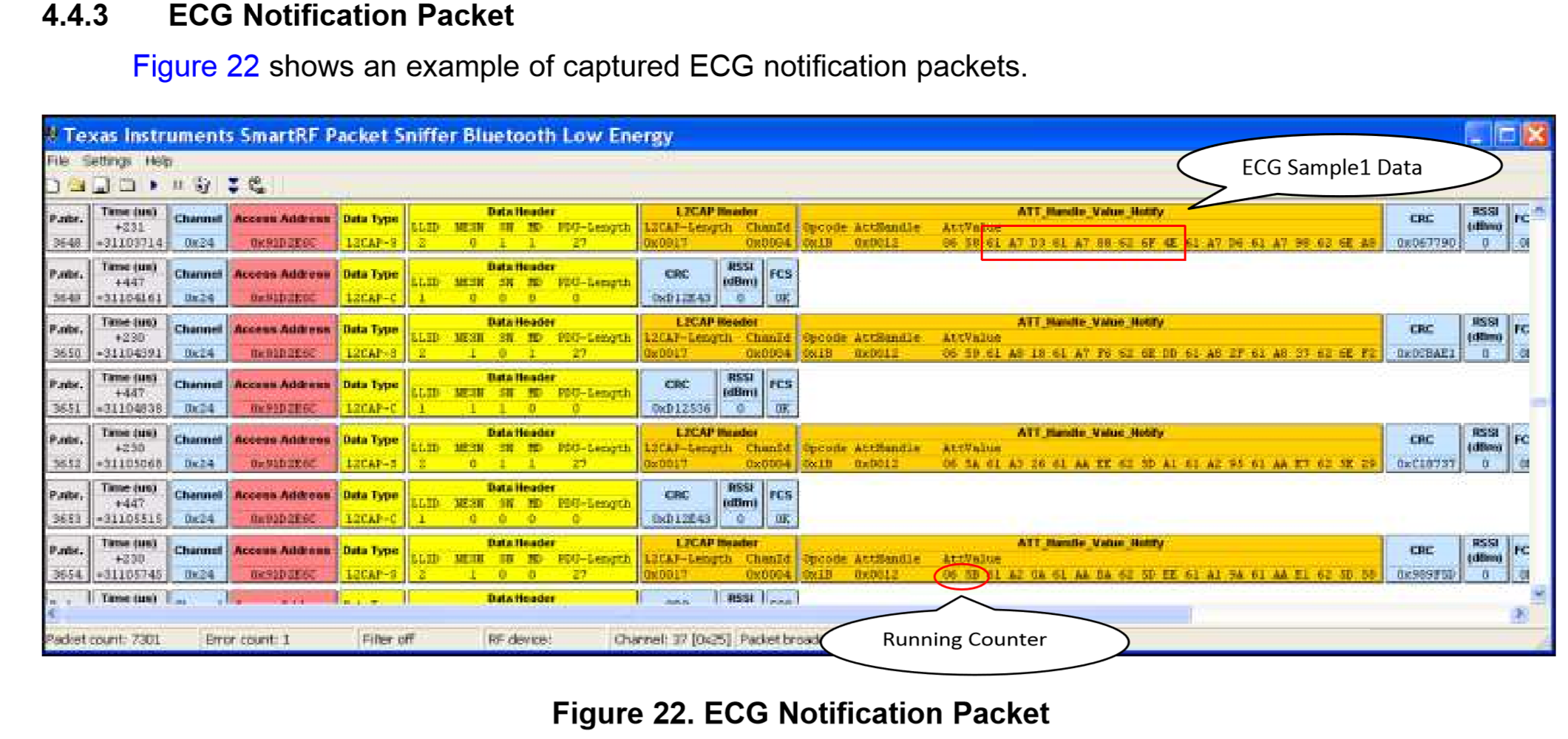
    What do these errors mean? I did not find adequate documentation. I was expecting to see the following like in the user guide:


    I'd really appreciate a response, thank you. 

  • Hussam,

    Section 4.4.2 of the reference guide (http://www.ti.com/lit/pdf/tidu195) explains this. Refer Figure 21 for ECG peripheral application "Complete Attribute Table"

    On power up, advertising is enabled and the peer device must discover and initiate a connection procedure to the ECG peripheral.

    Section 4.2 of this document http://www.ti.com/lit/ug/swru270c/swru270c.pdf explains establishing a connection using BTOOL.

    Thanks, Vishy


  • Hello Vishy,

    Thank you for your reply! I successfully established the link using BTOOL following Section 4.2. Are there other configuration settings that are needed? After running Packet Sniffer, I am not seeing the sample ECG packets like shown in Figure 22.
  • Hussam,

    Once link is established, you have to "Enable Notification" from ECG peripheral. Enable Notifications is explained in Section 4.3.6 of the same document you used to establish link.

    You will see the sample ECG packets once notifications are enabled.

    Thanks, Vishy

  • Hi Vishy,

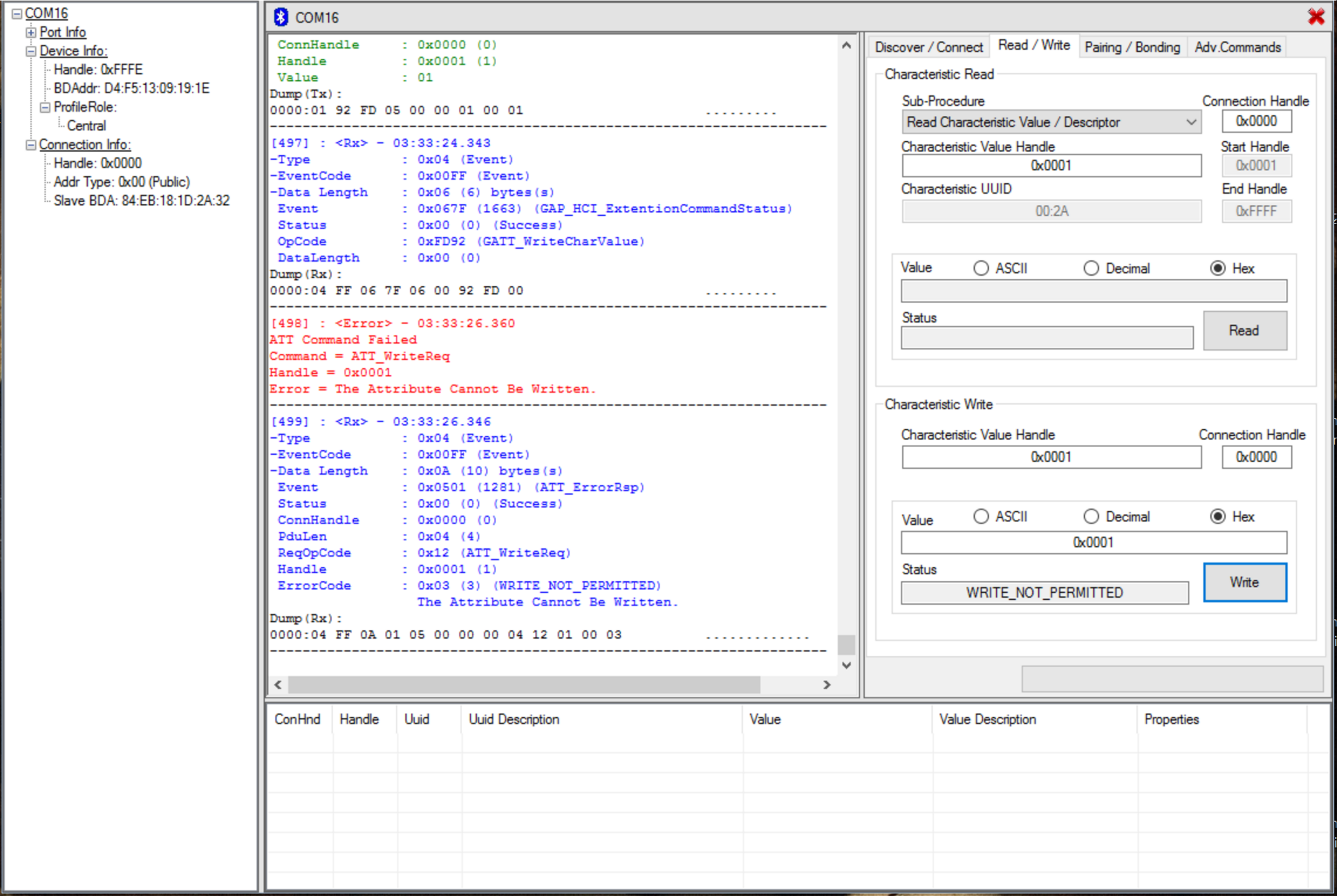
    The characteristic value handle is set to 0x0001, writing on the "Value" box give me the error below.

    [EDIT: I misunderstood, I just saw this document:

    http://processors.wiki.ti.com/index.php/LPRF_BLE_Simple_Application#Reading_Characteristics_by_UUID]

  • Hussam,

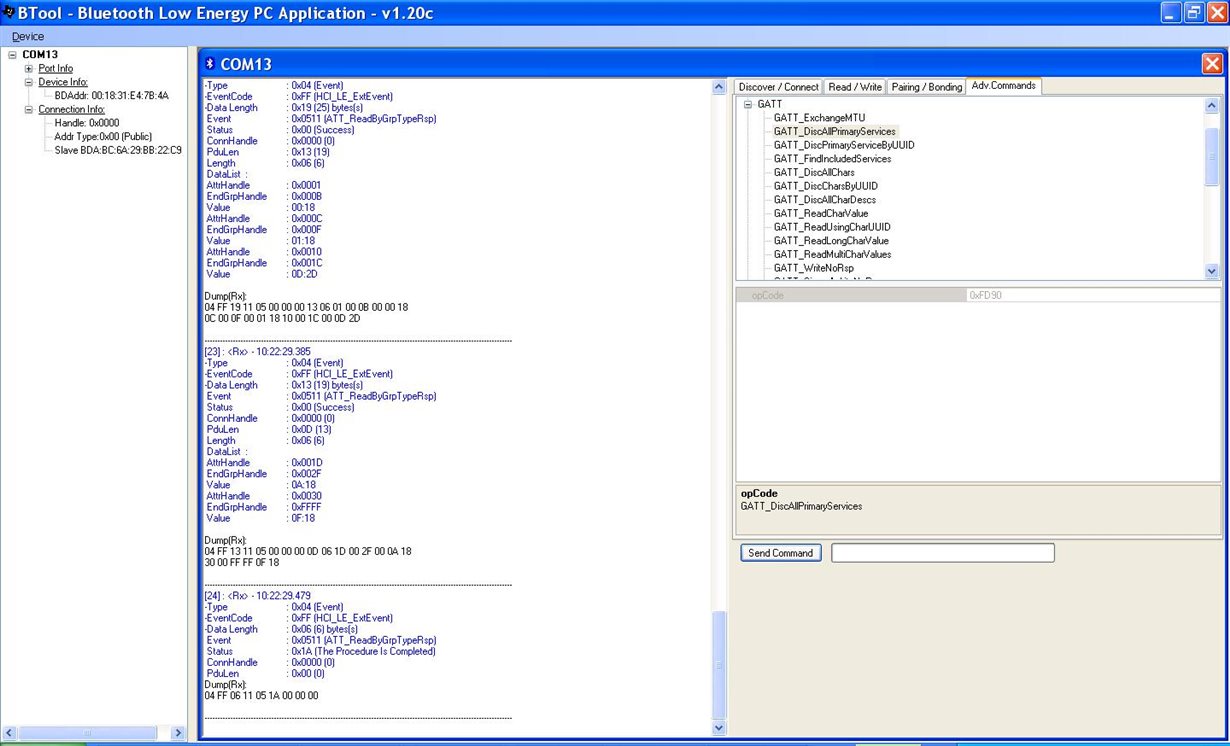
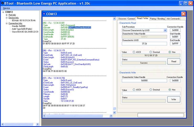
    Glad you found some document to help. Below are couple of screen shots I had (from 2 years back, BTOOL v1.20c) that might help you...

    a) From the BT tool, I send the GATT command “GATT_DiscAllPrimaryServices” (0xFD90) and I get two services “0x2D0D” and “0x180F”. 0x2D0D is the ecg service and 0x180F is the battery monitor service.


    b) Below I send the command GATT_DiscCharsByUUID) as shown below. You should see response 10 12 00 37 2D as shown below. If you look up the Complete Attribute Table shown in tidu195a document Figure 21, you will see handle corresponding to this UUID as 0x12.  And you have write to handle 0x13 the data "01:00" to enable notifications (again see the explanation in Figure 21 table)

  • Thank you Vishy for the procedure and screenshots!

    I'm not receiving the same outputs.

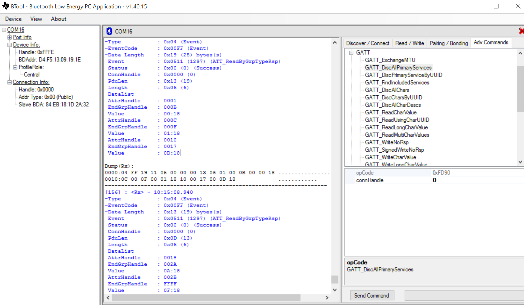
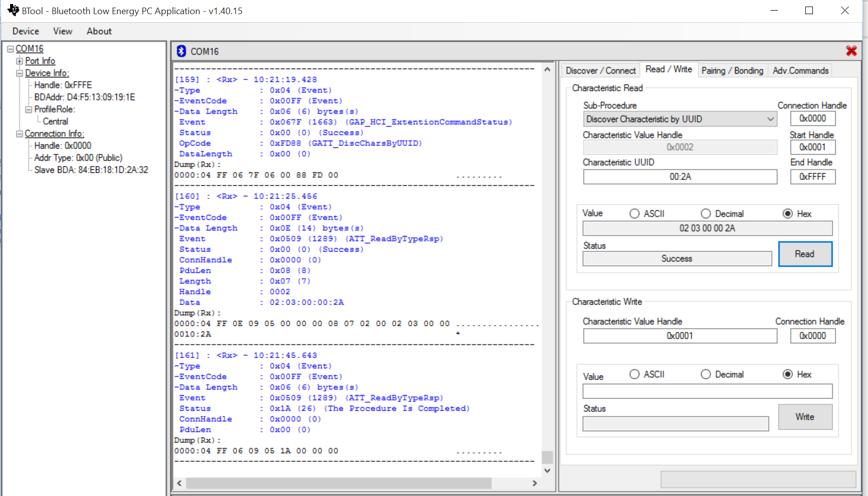
    1.) The Battery service 0x180F comes up but not the ECG service 0x2D0D. Instead I receive 0x180D.


    2.) The "Discover Characteristic by UUID" command gives me 0x2A00.


  • Hussam,

    I think you have loaded a wrong project code into the board. 

    Here I have enclosed the correct hex file to use (it's inside a zip). Please load this into your board using Smart RF Flash Programmer. You need CC Debugger to connect to the board and load via JTAG. JTAG port is on the back. 

    Thanks,

    Vishy

    ecg-v07.zip

  • Thanks Vishy, I flashed the board with that .hex file and after establishing a link, the ECG service 0x2D0D came up. I'm not sure what the problem was before, I used the heart rate example from the BLE stack to program the board using IAR. 

    I still have a few problems:

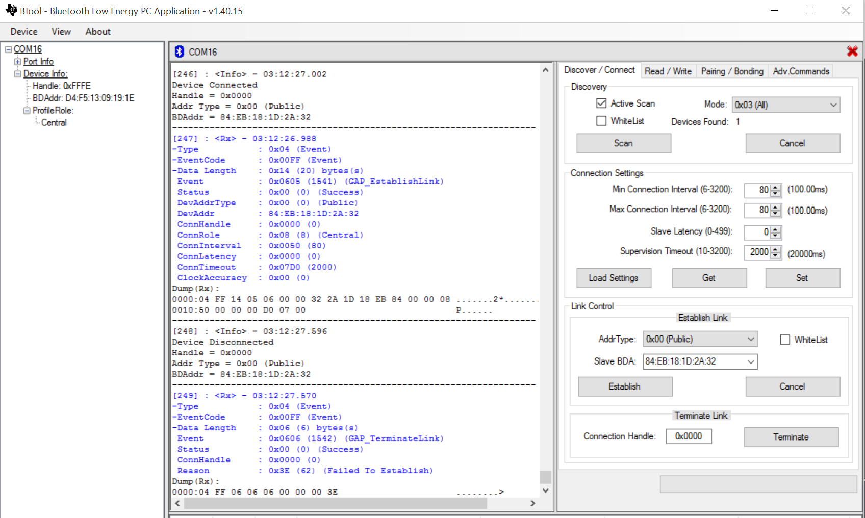
    1.) Establishing the link doesn't always occur. It always discovers the device but it takes many attempts to secure a connection. Usually I receive the below screenshot where the device momentarily connects but then immediately terminates. By chance a link is established and I'm able to work with that.

     
    2.) When I can establish a link, after verifying the service with the GATT_DiscAllPrimaryServices command, the GATT_DiscCharsByUUID command gives me a "Message Response Timeout" error. Or the device disconnects while the command is sent. I have not been able to confirm the 10 12 00 37 2D response. I'm not sure how to resolve that. Could it be an issue with the BTool firmware set I have flashed on the USB dongle?

  • You can obtain the firmware (with BLE stack) specific to that TI Design board from the following link
    www.ti.com/.../tidc262
    It has the heart rate IAR project (with ADS1293 SPI driver integrated) and that's the one I used to generate the hex file I sent you .
    Regarding (1), you can try modifying the connection settings. You have to talk to the BLE experts on this.
    Regarding (2), please check your CC2540 dongle has the correct firmware loaded. It works fine in my setup. I was also able to enable notifications.
    By the way, make sure jumper J3 and resistor R7 are shorted on the ADS1293 + BLE board.
    Thanks,Vishy
  • Vishy,

    I have J3 shorted on the board. I loaded the CC2540 dongle with "CC2540_USBdongle_HostTestRelease_All.hex" located at C:\Texas Instruments\BLE-CC254x-1.4.1.43908\Accessories\HexFiles\CC2540_USBdongle_HostTestRelease_All.hex. Can you direct this to the BLE experts so that I can properly modify the connection settings? Same problems persist, I haven't been able to enable notifications after establishing a link. I appreciate your help!
  • Hussam,

    I suggest you post the link connection issue as a new posting in this forum. so it gets the attention of BLE experts. I don't follow this forum. If you have other questions for me (that is related to this specific board or firmware), please post it as follow up on this thread.

    Thanks,

    Vishy

  • Dear Vishy,

    Can you please confirm that ecgMeasNotify(..) is where the ECG values are packed by below lines:

    ecgMeas.value[0] = (counter & 0xFF00)>>8;

    ecgMeas.value[1] = (counter & 0xFF);
    osal_memcpy(&ecgMeas.value[2], &send_buf[wptr * PKT_DATA_SIZE], PKT_DATA_SIZE);

    We are able to get some data by bluetooth in Android, but its is pure Noise. I believe that we are not able to parse the same data properly on Android side. In AdS1293, we are just using 2 leads - RA and LA, and as per spec, we are just extracing D2,D3,D4 bytes from the Bluetooth packet with below code in Android and plotting on mobile phone screen

    adc_data = ((uint32_t) read_buf[0] << 16)
    | ((uint16_t) read_buf[1] << 8) | read_buf[2]; // form raw adc output data
    adc_sample_array[i] = adc_data;

    As you know that iOS app of ecgmonitor.ipa, is no longer available, we are kind of stuck, can you please help to confirm if above is correct

    Thanks

    Rahul

  • Rahul,
    I will check about this. Did you see the protocol explanation in Section 4 of this document?
    www.ti.com/.../tidu195a.pdf

    Thanks,
    Vishy
  • Yes, that's the place where the ECG values are packed for sending. Note, the ECG data values are read from the device on DRDY interrupt (refer the corresponding interrupt service routine). Thanks.
  • Hi Vishy,

    Can you please share the code used in iOS or android to parse the ECG values back from 20 byte header.

    We are using below code in android, but even if we input sine wave output is noise only. We have J3 shorted and R7 shorted, can this be a source of prolem ?

    byte[] value = characteristic.getValue();
    for (int i = 0; i < value.length - 2; i = i + 2) {
    xCounter++;
    int y = ((value[i + 1] & 0xFF) << 8) + (value[i] & 0xFF);

    Thanks,

    Rahul

  • Dear Vishy,

    Need a quick help from you. When we read SPI data from below lines, do we just read 8 bit LSB or we have to read upper 8 bit and middle 8 bit too. Code that you have written in firmware is as below

    ecgMeas.value[0] = (counter & 0xFF00)>>8;

    ecgMeas.value[1] = (counter & 0xFF);
    osal_memcpy(&ecgMeas.value[2], &send_buf[wptr * PKT_DATA_SIZE], PKT_DATA_SIZE);

    So ecgMeas.value[0] and ecgMeas.value[1] looks like counter values which just keep on increasing. Hence do we just read ecgMeas.value[2] for valid SPI data ?

    Also you have set DRDY on Channel 1, which mean that for every interrupt channel 1 will get ECG data from SPI, but other Channels ( 2 &3] will get ECG data once every 6 reads of Channel 1 SPI data ? so don't we get extra Channel 1 ECG data ?

    Please suggest at the earliest

    Thanks

    Rahul
  • Hi Rahul.

    Just jumping in here with what I've learned on this topic...

    Incoming data (20 byte packets)

    [Dump Data][Counter 2 Bytes][Protocol/Error Data] every 17 packets


    [Dump Data][Counter 2 Bytes][CH1 CH2 CH3 CH1 CH2 CH3]


    CH data is 3 bytes [Highest Middle Lowest]


    Dump Data is any added data on top of the 20 bytes you expect. For example, if you use the USB dongle on the PC flashed for BTool, it will deliver a 31 byte packet in which you can ignore those extra 11 bytes. 

    Hope that helps!