Hello all,
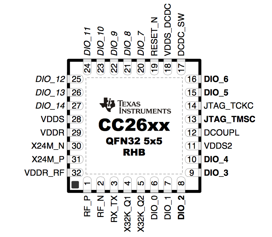
I've just recently gotten started learning about setting up JTAG debugging. I've got a cc2640 RHB package.
I'm trying to set up JTAG debugging for it. After reading around, I decided to go with the XDS100v3 and use 4 wire JTAG. I'm using a 14 pin header from SAMTEC, and looking at the pinout specified by TI in the image below.
It's pretty easy to understand how to wire the GND pins, TCK, rTCK, TDI, TMS, TDO, and VTRef. However, I'm confused as to how to wire the other pins - EMU0, EMU1, KEY, TDIS, nTRST, nor do I fully understand what they are for. I'd appreciate a little bit of help/clarification in how to set this up.
Thank you!


