This thread has been locked.

If you have a related question, please click the "Ask a related question" button in the top right corner. The newly created question will be automatically linked to this question.

NFC Implementation on TRF7970A Transceiver

Other Parts Discussed in Thread: TRF7970A, TIDM-NFC-TRANSCEIVER, MSP430F5529, TIDM-NFC-P2P, TIDM-NFC-EZ430-MODULE

Hi,

I am working on TRF7970A transceiver. I have explored.TRF7970EVM, MSP-EXP430F5529 with TRF7970ATB daughter card etc.


I am planing to implement "Tag reader" and "Peer-to-peer" mode with TRF7970A transceiver. My questions are in follows.

1. What should be the good starting point for the development?

2. How stable is the "Peer-to-peer demo provided by the TI? Will this be good point to start development from?

3. Does TI recommend any NFC stack for working with the TRF7970A?

Thanks,

Ali

  • you should use the TRF7970A BoosterPack + MSP-EXP430F5529 LaunchPad

    there is a soft bundle of these devices on the TI eStore ==> https://estore.ti.com/nfclink-bndl.aspx

    see the app note and reference design guide here - and the code there has a build option for the LaunchPad or the EXP boards. 

    http://www.ti.com/tool/TIDM-NFC-TRANSCEIVER 

    note in the design guide you will see how stable it is - the limitations we see are on the vintage of handset and you can notice that the newer handsets following the NFC Forum specs can interact with our part in passive and active, target and initiator, at all data rates. 

  • Josh,


    Thank you for the update.


    I have tried that code. It is working fine. The only issue I am facing is the time. As If I run P2P code after every say 500 milli second the code doesn't work. I have to run it quickly for 15-20 time without any delay to get it connected properly.

    This scenario is not very feasible if we are trying to run the NFC as a part of big system.

    Do you have any suggestion in this regard?

    Ali

  • which MCU platform are you running it on? something not to overlook is the jumper settings on the TRF7970A BoosterPack (if using the -F5529 LaunchPad) or the jumper needed on the -F5529 EXP board between P2.0 and P4.0 on header J12. This is the IRQ pin...on the BoosterPack its there to allow for support of both the -G2553 and -F5529 LaunchPads, on the EXP board it is there because we use interruptible GPIO instead of polling the GPIO, to conserve power

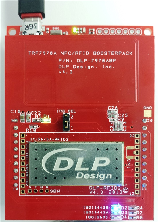
    See page 36 here ==> http://www.ti.com/lit/an/sloa192/sloa192.pdf if using the EXP board, and if using the BoosterPack, set jumper to IRQ_SEL = 1

  • Josh,

    I am using "MSP-EXP430F5529", jumper is connected between P2.0 and P4.0 on header J12.

    One more thing is what is the use of  "SYS_CLK" pin?

    Do you have any document for the complete explanation of the P2P demo code?

    Thanks,

    Ali

  • http://www.ti.com/lit/an/sloa192/sloa192.pdf


  • Josh,


    Thanks for the quick answers.


    Being a user of TRF7970A which things do I have to implement in my embedded code and which things will be taken care of by TRF7970A integrated protocol?

    Ali

  • the TRF7970A will handle all the CRC generation and checking, parity checking and bit timing. It is a register based transceiver device, which means in simple terms that your code must configure the device correctly for the protocol(s) you desire to use, have an interrupt handler and a command structure implemented to handle positive and negative operations. the example code that we have posted on the web is intended for you to use directly, so you don't have to re-create any of that on your own...at any rate, if you did want to recreate it, you can use it as a solid reference.


  • Hi Josh,

    Thank you for all your support.


    Do you have some documentation and source code for the NFC type-4 tag support with the TRF7970A transceiver?

    Ali

  • sure thing - we have setup NFCLink for showing/using for integrating P2P, CE and RW modes...see ==> http://www.ti.com/tool/nfclink and

    http://focus.ti.com/docs/training/catalog/events/event.jhtml?sku=OLT213023&DCMP=connectmore-smartgrid&HQS=connectmore-smartgrid-v2 

    standalone version is coming soon for those who don't need NCI. 

  • Thanks Josh.

    I have updated the code to work with MSP430F55229 experimental board. I am using MIFARE Desfire (type-4) tag. However correct data is not being read back from tag. Below is how the tag is working.

    1. UID read from NFC player (042E1992DA2C80) and from the standalone mode (042E19BB92DA2C80),  (Incorrect)
    2. NDEF Application Select, expected response (029000), actual response (029000), (Correct)
    3. Capability Container Select , expected response (039000), actual response (039000), (Correct)
    4. Read Binary (from CC), expected response (02,Data,90,00), actual response (02, Data, 85, 00), (Incorrect)
    5. Select NDEF File, expected response (039000), actual response (039000), (Correct)
    6. Read NDEF File, expected response (03,Data,90,00), actual response (03, Data, 85, 00), (Incorrect)

    Can you please suggest that am I missing some step or the response is OK?


    Do I need an NDEF translator after getting the data from NDEF file of type-4 tag?

    Do you recommend the NFC link library source (embedded) or the EVM source for porting purpose?

    When will  standalone version of the NFC link library available? Can you provide me some working copy of it so that I can work on it?


    Regards,

    Ali Zulqarnain Anjum

  • Ali - 

    so you are the one working with Jason Kriek

    as he may have informed you already - there must be a parsing error in the code after you ported it. 

    if you can provide back, we can fix it pretty quick for you i think

    the issue I see to start with is that you are getting back a response (in your #1) which is showing the first three bytes of UID and the BCC of that first round of anticollision. 

    the string should come back on the first round (because this is a double size UID) as 0x88, 0x04, 0x2E, 0x19, 0xBB - with 0xBB being the XOR (BCC) of the preceding bytes - but you should never see the 0x88 or the 0XBB being printed out on the screen. 

    the code section (in the iso14443a.c file, calling code witten in NDEF.c) handles the steps which result in reading out the binary and presenting it on the screen


    RATS(); //for ISO14443-4A card selection
    NDEFApplicationSelect(); //Selects NDEF Application D2760000850101
    CapabilityContainerSelect(); //Selects the Capability Container
    ReadBinary(0, 15); //for contents of the capability container
    SelectNDEF(); //Selects NDEF Application
    len = ReadBinary(0, 2); //reads NDEF Application for length of message
    ReadBinary2(2, len); //for NDEF content
    UartSendCString("NDEF Message: ");
    UartPutChar('[');
    for(j = 8; j < len+1; j++)
    //for(j = 34; j < 47; j++)
    {
    UartPutChar(buf[j]);
    }
    UartPutChar(']');
    UartPutCrlf();


  • Ali - 

    Jason says that worked out for you, so this is what i came up with for the rest of what you reported you were having trouble with. 

    so then your remaining items are to use the ReadBinary and ReadBinary2 functions (shown below in the order, first one is to get capability container, then the length of the NDEF message (this is Nlen) and then he needs to readout the NDEF message itself)


    • NDEF Application Select, expected response (029000), actual response (029000), (Correct)

    (no issue here)

    • Capability Container Select , expected response (039000), actual response (039000), (Correct)

    (no issue here)

    • Read Binary (from CC), expected response (02,Data,90,00), actual response (02, Data, 85, 00), (Incorrect)

    This function (Read Binary) returns contents of the capability container….which is not what you are expecting it seems, but it should be.

    see  below in code snippet.  (first function)

    • Select NDEF File, expected response (039000), actual response (039000), (Correct)

    (no issue here)

    • Read NDEF File, expected response (03,Data,90,00), actual response (03, Data, 85, 00), (Incorrect)

    The function you should be using here again is (ReadBinary) to get return of Nlen….which is not what yoiu are expecting it seems, but it should be.

    see  below in code snippet.  (second function)


    • Then i think you are missing using ReadBinary2 function a second time to actually read the message, based on the value returned by using the ReadBinary function

    see (first use of second function)


    ……….

    CapabilityContainerSelect();                           //Selects the Capability Container

    è this is first function è                    ReadBinary(0, 15);                                     //for contents of the capability container

                                                    SelectNDEF();                                          //Selects NDEF Application

    è this is second use of first function è      len = ReadBinary(0, 2);                                //reads NDEF Application for length of message

    è this is first use of second function è      ReadBinary2(2, len);                                   //for NDEF content

                                                    UartSendCString("NDEF Message: ");

                                                    UartPutChar('[');

                                                    for(j = 8; j < len+1; j++)

                                                    {

                                                           UartPutChar(buf[j]);

                                                    }

                                                    UartPutChar(']');

                                                    UartPutCrlf();

    …………..

  • Josh,

    Thanks for the answer. I have also sent following data to Jason.

    I am able to read the correct NDEF data from the tag if the NDEF data length is up to five bytes. However as the NDEF data length exceeds the from five bytes incorrect data is being read back. I am using Stollmann NFCPlayer (received with the NFC link library) for writing the tags.


    Below is response from the ReadBinary2(2, len);” function (the complete received buffer).


    Data in the tag : “SSS”

    Response : 03 D1 01 06 54 02 65 6E 53 53 53  (Correct)


    Data in the tag : “SSSSSS”

    Response : 02 91 3D 00 60 00 30 00 B0 00 02 0D E1 04 00 (Incorrect)

     Do I need extra steps for parsing the data greater than 5 bytes?

    Thanks,

    Ali


  • Josh,


    So far I have explored everything there is to explore about the TRF7970A, MSP430F5529, NFC player, tag reads etc.

    Now I am moving towards the implementation phase.

    Where would you suggest to import code from? evaluation module code, NFC link library source or some other example?

    When will be the standalone version of NFC link library available, can you provide me some working code?


    Thanks,

    Ali

  • Ali - 

    if you are using MSP430F5529 (or other 5xx family member) - then either the host based code (if using a host in your end product) or the standalone code should serve you well. 

    http://www.ti.com/tool/TIDM-NFC-TRANSCEIVER (this is NFCLink, host based with NCI) 

    http://www.ti.com/tool/TIDM-NFC-P2P (this is standalone P2P, the team is adding CE and R/W to this, currently testing and debugging for release later this year)

    if you are intending on using smaller MCU, this example might be a good one to use for starting ==> http://www.ti.com/tool/TIDM-NFC-EZ430-MODULE 

  • i think you might need to clean the tag - i am not seeing same thing on my side, the code we provided should handle the NDEF messages of variable sizes...you can see below here where i am using NFCLink to read Type 4A tag with your SSSSSS and then the -G2553 BoosterPack code to read out same.

  • Josh,

    Thanks for the reply.


    I am getting the incorrect result at my end.

    Following is my readbinary2() function.

    unsigned char ReadBinary2(unsigned char Offset, unsigned char Read_Length)
    {
      /*~~~~~~~~~~~~~~~~~~~~~~~~~~~~~~~~~~~~~~~~~~~~~~*/
      unsigned char Nlen=0;
    //  extern unsigned char Tag_found;
      /*~~~~~~~~~~~~~~~~~~~~~~~~~~~~~~~~~~~~~~~~~~~~~~*/

      RXErrorFlag = 0x00;

      buf[0] = 0x8f;
      buf[1] = 0x91;
      buf[2] = 0x3d;
      buf[3] = 0x00;
      buf[4] = 0x60;  // length
      buf[5] = 0x03;
      buf[6] = 0x00;
      buf[7] = 0xB0;
      buf[8] = 0x00;
      buf[9] = Offset;              // offset
      buf[10] = Read_Length;       // Read Length


       TRF79x0_rawWrite(buf, 11);
      Trf7970ResetIrqStatus();
     //irqON;
       P2IE |= 0x01;

      i_reg = 0x01;
      RXTXstate = 0;                            /* the response will be stored in buf[0] upwards */

    CounterSet();
      countValue = count1ms * 20;              /* 20ms for TIMEOUT */
      startCounter;                          /* start timer up mode */

      while(i_reg == 0x01);   // Wait for end of TX


      i_reg = 0x01;

      //RESET_COUNTER;

      CounterSet();
      countValue = count1ms * 20;              /* 20ms for TIMEOUT */
      startCounter;                             /* start timer up mode */

      while(i_reg == 0x01);                     /* wait for RX complete */

     // RESET_COUNTER;
    // Trf7970ResetIrqStatus();

      // might need test case here, like if(i_reg == 0xFF)
       Nlen = buf[2];
       MCU_delayMillisecond(1);
          
       return Nlen;
    }

    Following is the call sequence to the functions.


                    RATS();                                        //for ISO14443-4A card selection
                    NDEFApplicationSelect();                    //Selects NDEF Application D2760000850101
                    //HCE_ApplicationSelect_1();                    //Selects HCE Example 1 from Android SDK F0010203040506
                    //HCE_ApplicationSelect_2();                    //Selects HCE Example 2 from Android SDK F0394148148100
                    CapabilityContainerSelect();                //Selects the Capability Container
                    ReadBinary(0, 15);                            //for contents of the capability container
                    SelectNDEF();                                //Selects NDEF Application
                    len = ReadBinary(0, 2);                        //reads NDEF Application for length of message
                    ReadBinary2(2, len);                            //for NDEF content
                                       //UartSendCString("NDEF Message: ");
                    //UartPutChar('[');

    Here I read the response buffer which I shared in earlier email.
                    for(j = 8; j < len+1; j++)
                    {
                        debuggingInfo[m] = buf[j];//UartPutChar(buf[j]);
                                            m++;
                                           
                    }
                      DisplayDebugInfo(debuggingInfo,m);
                        //UartPutChar(']');
                        //UartPutCrlf();

    I am very confused that why the code is not working for size greater than 5.

    Ali

  • can you send over the -F5529 project you have created? the code is working on -G2553 platform for all sizes on my side. 

    i have -F5529LP and EXP board on hand to use.  

  • Hi Josh,

    I am facing a little problem with the reception process of the TRF7970A. No matter how much bytes are available for the reception the register ( 0x1C) gives maximum of 62 bytes. The reception of number of bytes <62 is flawless but when the bytes increased than 62 bytes than the register (0x1C) only shows that 62 bytes are avaiable in the FIFO.

    can you suggest what can be the issue?

    Thanks,

    Ali

  • what value are you sending for b4 - b1 in Param2 in ATTRIB command to the tag? This is what tells the PICC (tag) how big a frame can be received by the PCD (reader) Param 2 is the seventh byte in the ATTRIB command, where 0x1D is the first byte considered. 

    0x1D(one byte)    1

    PUPI(four bytes)  2, 3, 4, 5

    Param1(one byte) 6

    Param2(one byte) 7 <== in this byte, you should have upper nibble telling tag the baud rate to operate at, lower nibble is max frame size indication

    Param3(one byte) 8

    Param4(one byte) 9

  • Hi Josh,


    Thank you for all the prompt answers. I have implemented the type-2 (MIFARE ultralight C) and Type-4 (NXP Desfire) tag read functionality in my device.

    Next in line is peer-to-peer mode. I have imported the code from F5529 example code. My device is successfully creating a P2P connection with the MSP-430F5529 experimental board.

    I have Samsung Galaxy note-2 and Sansung S-4 smart phones. Both phones are creating the P2P connection with MSP EXP board successfully. However only S-4 is creating a P2P connection with my device and Note-2 is not creating a P2P connection.

    Can you suggest what can be the issue?

    Also there is a function IS_IRQ_SET() which we check in the interrupt service routine for the transceiver.. What is the usage of this function?

    Thanks,

    Ali

  • regarding the Note 2, if you have a look on the application note, tables 6 & 7, pages 33 & 34 respectively - you will see the Note 2 has some limitations.

    regarding the IRQ question, do you mean IRQ_PIN_SET? look in mcu.h and config.h files to see that IRQ is being setup on GPIO pin as input. Is this matching what you are expecting?

  • Josh,


    Thank you for the answer.


    Yes I am referring to IRQ_PIN_SET. I know that this is checking the status of IRQ pin. but what is its significance? Interrupt is already served in ISR(vector 2). So why checking the pin here?

    Can the example code modified to act as a target and wait for the initiator interrupt? Any suggestions?

    Thanks,

    Ali

  • well - the pin on the MCU that the TRF7970A needs to be identified/mapped and configured as input before it can be used. Make sense? 

    the example code does both target and initiator...there is a nfc_target.c file even...and if you use the GUI that comes with the download package you can select only target mode and different bit rates as you choose.

     see section 8 ==> http://www.ti.com/lit/an/sloa192/sloa192.pdf

  • I understand the pin configuration. But my point is that why do we have to monitor the pin status in the transceiver's ISR. 

    if (IRQ_IS_SET())
     {
            g_ui8IrqFlag = 1;

     }


    I want to implement a standalone mode for p2p communication. The way example code behaves is now that we configure the transceiver as an target and wait for the interrupt. I want don't want to wait for the command. I want to configure the transceiver as target and do other tasks. When the interrupt occurs I will go serve the P2p protocol.

    Thanks,

    Ali

  • Ali - 

    from our point of view it is implemented as standalone - however i understand your situation - the problem is that as a target, you need to be able to respond within a certain about of time. the way it works now, when flag gets set the handler services the interrupt. if you want o "Do something else" then you will need to modify so that the handler gets called when the flag is set from your other "Do something else" loop, in a timely manner. You may be successful doing that, but you need to make sure you stay inside the specified times of the standards being used. 

  • Hi Josh,

    I got your point. I will keep you posted with my solution.

    I am facing one more problem. The code takes almost 495 mSec in one go. The code works fine if there is there is no other task beside it. However if I run another task which takes approx. 335 mSec after each turn of the P2P code. The P2P connection is not established.

    Can you suggest what can be the issue?

    Thanks,

    Ali

  • Hi Josh,

    For more clarification.

    If I run the P2P code without any delay then P2P connection is established successfully. However if i put the delay even of 1 mSec in between two consecutive calls of the function then P2P connection is not established.

    My questions are in follows.

    1. Is the behavior explained above is normal?

    2. Is there any way to  check the presence of any other device in the vicinity, and then start the P2P communication?

    Thanks,

    Ali

  • Ali - 

    please review section 2 of the app note ==> http://www.ti.com/lit/an/sloa192/sloa192.pdf 

    this covers what the code is doing regarding checking for another device being present prior to turning on its own field. it follows the NFC Activity spec, so if you are inserting delays in the wrong places, then you could be affecting the timings that are required by the activity, operational/digital specs.

  • Hi Josh,

    Thank you for the prompt reply.

    Here is my problem statement. Actually I want to run the P2P in standalone mode. The problem right now is that I have some other tasks as well to run alongside the P2P task. If I keep to running the P2P task then it wont satisfy my requirements. I want to update the example code in such a way that my device stay configured as a passive target and as soon as another device comes in its range it switch to P2P task and after that keep on running that until all the information is transferred. My device should be able to create the P2P connection with smart phone and with another instance of itself as well.

    Please share if you have any idea of how to use this example code to set the device in passive target mode (process start on interrupt) .

    Thanks,

    Ali

  • Hi Josh,

    Please tell me id my above mentioned question is ambiguous.


    Thanks,

    Ali