Hello all,
I'm developing a driver for the TRF7963A RFID chip. It should be able to detect and communicate with
a single ISO 14443-2/3B tag, ie only single slot anti-collision needed.
Despite being able to transmit, I'm not getting any responses.
The transmission happens without a problem, I get the TX and no-response interrupts as expected, but
no RX interrupt.
I have two HW setups that I've tried this on: proprietary HW with MSP430F5438A and TRF7963A, and a TI development
board with RFID dev board according to the following (until I can reliably read tags on the TI dev boards
I won't move to the proprietary HW just in case).
The TI dev board setup is as follows: Trxeb-board using a msp430f5438a and a CC2520 radio. A TRF7960ATB dev board
mounted on a SmartRF06 dev board and jumper cables for SPI, IRQ, and EN. EN2 is fixed to ground. The board is
powered from the Trxeb, ie 3.3V.
I know the ISO protocol is picky and tags won't respond unless a correctly formed request is sent, and I follow
the ISO 14443B protocol. The WUPB I transmit looks like this:
0x05 WUPB magic byte
0x00 AFI == all families and sub-fam's.
0x08 Single slot WUPB, not extended ATQB
To send this WUPB I do the following.
I set ISO register to 0x0c, ie ISO14443B_106_KBPS (I've tried the high bitrate 14443B's as well),
then waited for 7 ms before writing the following over SPI:
0x8f reset
0x91 transmit with CRC
0x3d burst write to FIFO len reg
0x00 0 bytes
0x30 3 bytes len
0x050008 the WUPB
which follows every documentation I've found, and the example code.
At this point in time (just before the above SPI transaction), the registers have the following settings:
CHIP_STATUS_CONTROL 0x01
ISO_CONTROL 0x0c
ISO14443B_TX_OPTIONS 0x00
ISO14443A_HIGH_BIT_RATE_OPTIONS 0x00
RX_NO_RESPONSE_WAIT 0xff
RX_WAIT_TIME 0x01
MODULATOR_AND_SYS_CLK_CONTROL 0x10
RX_SPECIAL_SETTING 0x40
REGULATOR_AND_IO_CONTROL 0x87
IRQ_STATUS 0x00
COLLISION_POSITION_AND_INTERRUPT_MASK_REGISTER 0x3f
COLLISION_POSITION 0x00
RSSI_LEVELS_AND_OSCILLATOR_STATUS 0x40
TESTA 0x00
TESTB 0x00
FIFO_STATUS 0x00
TX_LENGTH_BYTE1 0x00
TX_LENGTH_BYTE2 0x00
No complex stuff. I relaxed the wait and no-response times to allow for slow tags, but no luck.
I've implemented and handles the five erratas found in SLOA140. And PLEASE, these are erratas and the document
should be named appropriately, not "Using the SPI interface with TRF7960"! This is really crappy, I (thought I had)
functioning SPI and hence didn't look in this document. Not until I saw it mentioned in a stray e2e thread did
I understand it was an errata document!
Namely:
SPI CLK polarity diff between reading and writing
IRQ status reg not cleared - now burst reading one byte more to clear it
Single-byte commands need an extra clock cycle - implemented, see screenshots
Wait, no-response defaults are bad - manually set to maximum relaxed setting as above
tx single byte - implemented the fix as described in the document
Now I'm at my wits end and am stabbing in the dark on what the error might be.
Can a TI rep please sanity check the register settings and my screenshots to see if my errata fixes are proper?
Any other clues/hints/suggestions?
Is it required to command stop decoders, start decoders as in some of the example code?
Unfortunately I have no access to RF analyzers to verify that anything is actually sent, but I have previously
communicated with both the 14443B tag and with a ISO15693 tag (Tag-it HF) but something has apparently changed.
More information: I'm not using the example code for a number of reasons. For one, this has to play well with
an OS and as such I cannot allow the driver to hold the CPU as in the example code.
Screenshots:
first, sending the WUPB

then we get a EOTX interrupt and read it out:

sending a command (here FIFO reset) includes the errata fix:

then we get the noresponse interrupt:

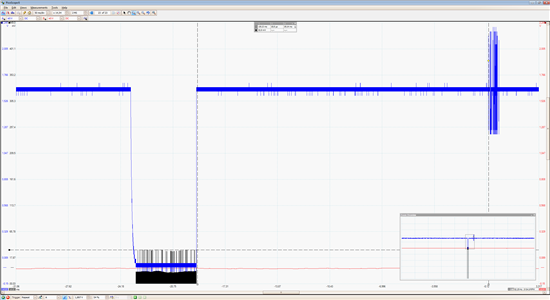
this is the time it takes for the device to transmit, from start of SPI to EOTX:

this is the time from EOTX to no-response: