This thread has been locked.

If you have a related question, please click the "Ask a related question" button in the top right corner. The newly created question will be automatically linked to this question.

AM3358 interface with NFC TRF7970

Other Parts Discussed in Thread: AM3358, LINUX-NFC-TRF7970A, TRF7970A

Hi,

currently i am design the system according to TRF7970 data sheet schematic circuit. (i.e. TRF7970 connect with MSP430F23 and MSp430xx output to main MCu AM3358) Figure-1.

Can i connect AM3558 MCU directly with TRF7970 NFC IC with out using MSP430F23 IC (as shown in figure-2).

Please see the block diagram (attached) for understand my question.

If yes please share the reference schematics design for this.

(as per hardware point of view it can be connect, but as per software is it possible?)

http://e2e.ti.com/support/arm/sitara_arm/f/791/t/385710.aspx

  • Usman - 

    You have great timing....see ==> http://www.ti.com/tool/LINUX-NFC-TRF7970A 

    we just released this on Tuesday. I think its exactly what you are looking for

    Please check it out and let us know if it is OK with you or you see something which is missing. 

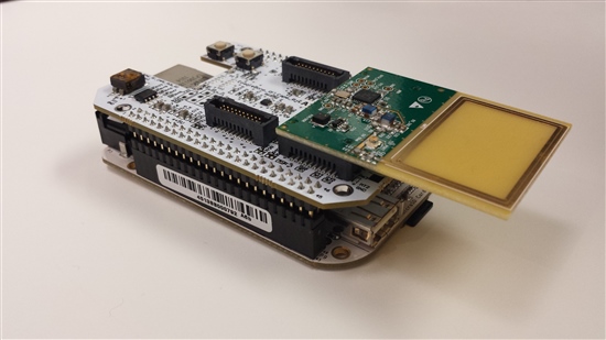
    HW used here was TRF7970ATB and BeagleBone + RF Cape, so schematic for connection the TRF7970ATB is found here: 

    http://www.ti.com/lit/pdf/tidr502

  • Hi Josh,

    its looks great. Its seem fine for my use.

    I need just 1 more help for connection of "net name = SYS_CLK" (at pin9 of connector P1 ). 

    if i want to connect this directly with Beagle Bone Black (BBB) what will be the connection?

    is this use SPI interface at BBB and what about SYS_CLK net of TRF7970A (at pin9 of connector P1).

    Previously, while using MSP430F23xx  with TRF7970A, we have connected this net SYS_CLK (of TRF7970A pin#27) with XIN/P2.6 (of MSP430F23xx pin#2). but in this new at which pin of beagle bone black i have to connect this ?  

  • you won't need to connect SYS_CLK, as this is output from TRF7970A...AM335x devices run at much higher clock than what comes out there - its purpose is to provide clock to an MCU (not MPU) if they system needs a reduced BOM and can handle HF clock in. That is what the example on the TRF7970AEVM is showing an example of.

  • Hi Josh,

    1 last thing what about ASK/OOK signal (pin 12 of TRF7970A) in previous circuit it was connected at MSP430F23xx I/O.

    in this new schematics this signal is connected at pin 18 of Connector P2. Kindly tell that at BBB where i can connect this signal? what is the purpose of this signal.


  • ASK/OOK pin should be pulled down via 1k Ohm resistor and can be connected to GPIO, too to accomplish the pulldown - but only needed if you wanted to use Direct Mode 0 or Direct Mode 1 or needed to have a look at signals during debug. The example we have provided with Linux uses Direct Mode 2 (default for the TRF79xxA devices) and is complete enough you should not have to use that pin for anything. So my recommendation is that you connect it and the MOD pin to pull down resistor (and a test point, too, if you like) and you will be OK

  • Hi Josh,

    as mentioned in your above feedback;

    HW used was TRF7970ATB and BeagleBone + RFcape,

    please can your share the schematics for RF Capes? which kind of hardware design used in that board? 

    or may I use Beaglebone Black (AM3358 MPU) + TRF7970 without RF Capes, directly? as this schematics provided (connect MOSI MISO signal directly to MPU).

  • Usman - 

    the schematics for the RF Cape are hosted here ==> https://github.com/CircuitCo/BeagleBone-RF-RevA1/blob/master/BeagleBone-RF-RevA1-schematic.pdf 

    Parent directory is: https://github.com/CircuitCo/BeagleBone-RF-RevA1

    connection to the TRF7970ATB was made via EM2 RF1 and EM2 RF2 (connectors on end of the board)

    Like this:

  • Hi Josh,

    how are you?

    Can you provide the board lay out design file for "TRF7970A EVM"

    i have found schematics and BOM only.

    TRF7970A EVM

    http://www.ti.com/tool/trf7970aevm?keyMatch=TRF7970A%20EVM&tisearch=Search-EN

  • Hi Josh,

    How are you?

    i need your help regarding the design files for TRF7970ATB evm , as i am using this on SPI interface . you have already share the schematics for this i need the board design file for this i have to know about the connector spacing and placement distance etc.

  • Hi Josh,

    I need the alitum / CAD (layout) files for TRF7970ATB  i have to draw the same antenna in my project PCB. because I am using TRF7970 with AM3358.

    Please share the CAD file (of TRF7970ATB) and antenna demission for this EVM.

    I have checked the TRF7960 EVM files but did not find any CAD file and PDF which have the antenna dimensions