This thread has been locked.

If you have a related question, please click the "Ask a related question" button in the top right corner. The newly created question will be automatically linked to this question.

CC3000 inconsistent

Other Parts Discussed in Thread: CC3300

I am working on interfacing CC3000 module with Atmel Xmega microcontroller. I have ported over the complete code for Basic Wifi Example to Atmel. 

Issue I am facing is that the code works occasionally. Sometimes it works and sometimes it just doesnt. On the Logic Analyzer, the values that I get on read dont seem to match all the time. What sort of information would you need to help me debug this issue ?

Thanks

  • Our host controller is sending the HCI_CMND_SIMPLE_LINK_START command as specified in the CC3000 Serial Port Interface. The timings also match what is expected.

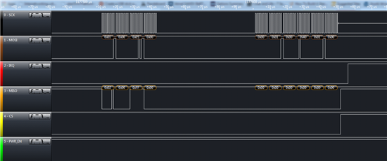
    The issue we are seeing is when the next step happens which is HCI_CMND_SIMPLE_LINK_START command complete. The data that is sent by CC3000 is not correct and the state machines gets stuck there waiting for the right data.

    I have also attached a session captured from the Saleae Logic Analyzer. You might have to download the software to open the session. 

    CC3000.rar
  • Hi Hardik,

    You should be sending 10 bytes request (0x03 followed by 9 bytes) on MOSI to get a 10 byte response. I see that the data on MOSI is not correct. Can you please check this? Also, there is a glitch on the IRQ line. This is not retaining the state after Chip select was moved to active high.

    Thanks & Regards,

    Raghavendra

  • Hello Raghavendra, 

    Thanks for the reply. The amount of bytes request to be sent (0x03 followed by 9 bytes) is dependent on the data payload length returned by CC3000. So if the CC3000 would have returned the current response, it would have been 10 byte response. I am seeing that when occasionally I get the correct response from the module. The response for HCI_CMND_SIMPLE_LINK_START command from CC3300 is inconsistent hence these issues. 

    The IRQ glitching is something that comes from CC3000 right ? For the Atmel micro that I am using its configured as an input that is pulled up internally. 

  • Hello, 

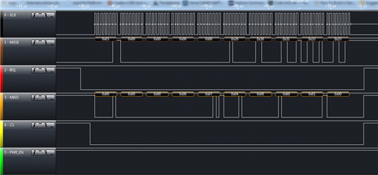
    I removed the internal pull up on the WIFI_IRQ line. I am not seeing the glitching but the command complete values from the CC3000 are still not consistent. 

    Please have a look at the waveforms

  • Hi Hardik,

    The timing looks alright now. It looks to me as if CC3000 is not given enough voltage. I am not sure about the module that you are using, and how Atmel drives the SPI lines. May be the below link could give you some pointers:

    http://e2e.ti.com/support/low_power_rf/f/851/p/306916/1069629.aspx#1069629

    Thanks & Regards,

    Raghavendra

  • Hi Raghvendra, 

    I checked the voltage levels on all the pins, it goes upto 3.3V

    Do you think applying a patch would maybe help things ?

  • Hi Hardik,

    Things should work even without the patch. But with the patch, it would be much stable. Such inconsistencies are seen in cases where patch download was aborted. You can try with the latest patch programmer.

    Thanks & Regards,

    Raghavendra

  • Hi Hardik,

    If you cant get this to work then you wont get the patch programmer to work either since the cc3000 startup is the same either way.  I have the the cc3000 working with the 32a4u, but I could never get the timing correct with the software from TI, so kudos on getting this far, I had to write my own software from scratch which has had its benefits, but not without a lot of work on my end.  That being said it looks like you are really close and something is probably wrong with your xmega spi settings. Could you post your settings?  Here are mine:

    //ENABLE SPID FOR MASTER MODE AS FAST AS POSSIBLE IN MOTOROLA SPI MODE 1 W/ MSB 1ST
    SPID.CTRL = SPI_CLK2X_bm | SPI_MASTER_bm | SPI_MODE_1_gc | SPI_PRESCALER_DIV4_gc;//16MHZ SPI CLK
    SPID.CTRL |= SPI_ENABLE_bm;

    It may also be an issue with how you are receiving data here is a snipet of my receive command function:

    WIFI_CS_ENABLE;
    for (ReceiveCmdTempVar=0;ReceiveCmdTempVar<10;ReceiveCmdTempVar++)
    {
    SPID.DATA = ReadPacket[ReceiveCmdTempVar];
    while(!(SPID.STATUS & SPI_IF_bm)){}//WAIT UNTIL REGISTER IS EMPTY
    ReceiveHeaderBuffer[ReceiveCmdTempVar] = SPID.DATA;//clear the interrupt flag for spid
    }
    ReceivedDataSize = (ReceiveHeaderBuffer[4] + (ReceiveHeaderBuffer[3] * 0x100)) - 5;

    if (ReceivedDataSize)
    {
    ReceiveCmdTempVar=0;
    do
    {
    SPID.DATA = ReadPacket[ReceiveCmdTempVar%10];
    while(!(SPID.STATUS & SPI_IF_bm)){}//WAIT UNTIL REGISTER IS EMPTY
    ReceivedDataBuffer[ReceiveCmdTempVar] = SPID.DATA;//clear the interrupt flag for spid
    ReceiveCmdTempVar++;
    }while(ReceiveCmdTempVar < ReceivedDataSize);
    }
    CLEAR_WIFI_INTERRUPT_FLAG;
    WIFI_CS_DISABLE;

    This uses two buffers one for the 10 character header which is always there and and one for the data if it is there.  

    Hope this helps,

    Chad 

  • Hey Chad, 

    I am setting up the SPI using the ASF library.

    spi_master_init(&***);
    spi_master_setup_device(&***, &wifi_cs,SPI_MODE_1,16000000,1);

    I am setting it to Mode 1 and on 16MHz clock. 

    For SPI read and write, I am using the functions from CC3000 and modifying it to work with Atmel. 

    void
    SpiWriteDataSynchronous(unsigned char *data, unsigned short size)
    {
    spi_write_packet(&***, data, size);
    }

    void
    SpiReadDataSynchronous(unsigned char *data, unsigned short size)
    {
    long i = 0;
    unsigned char *data_to_send = tSpiReadHeader;

    for (i = 0; i < size; i ++)
    {
    ***.DATA = data_to_send[i];
    waitspi();
    data[i] = ***.DATA;
    }
    }

    The device seems to be kind of inconsistent. Are you using CC3000 in any of your products ? Whats your views on its performance ? 

  • Hello, 

    I was able to get to the point where it prints "Example App:driver version 1.1.1.13". 

    I keyed in "01" in the putty window for it to enter Smart Configuration Mode. The LED starts blinking as per the code. 

    Now I tried the Ti smart Config App in my iPad. It doesnt connect. The LED is just blinking continously which means the Smart Config is not done. I tried the same thing through my phone by following the video tutorial as per http://www.youtube.com/watch?v=fxP9hnZysgo. It still doesn't connect and LED continues to blink. 

    In the app, I have set the device name to "CC3000" as that's what is defined in the main file. 

    char device_name[] = "CC3000";

    I have also defined the following in my main file so that the SMART CONFIG is unencrypted.

    #define CC3000_UNENCRYPTED_SMART_CONFIG

    Is there a way to see what the iPad is sending out ? Are those packets broadcast packets?

  • Hi Hardik,

    Did you get a chance to try with a different phone? CC3000 does not support MIMO. In such cases, the information may not be propogated.

    Thanks & Regards,

    Raghavendra

  • Hi,

    You can see those packets in monitor mode using Windows Network Monitor.  I had to see them to figure out a dumb issue I was having.  I had one character wrong and did use the broadcasts to figure it out.

    That being said you need to debug and see if the CC3000 is returning smart config finish(opcode 8080).

    Packet I send:

    SMART CONFIG START - NOT ENCRYPTED (ENCTRYPTED)-SEND
    WRITE LENGTH - SPI HEADER     TYPE OPCODE DATA
    0X01  0X00 0X09 0X00 0X00 0X01 0X0A 0X00 0X04 0X00(0X01)
    SMART CONFIG START - SEND(CONT)
    DATA
    0X00 0X00 0X00 0X00

    response to packet:

    SMART CONFIG START - NOT ENCRYPTED (ENCTRYPTED)- RECEIVE
    RESPONSE     LENGTH - SPI HEADER TYPE OPCODE DATA
    0X02 0X00 0X00 0X00 0X09 0X04 0X0A 0X00 0X05 0X00
    SMART CONFIG START - RECEIVE (CONT)
    DATA
    0X00 0X00 0X00 0X00

    response due to CC3000 receiving smart config data from app:

    SMART CONFIG DONE - NOT ENCRYPTED - RECEIVE - DUE TO APP SCAN
    RESPONSE     LENGTH - SPI HEADER TYPE OPCODE DATA LNG PROFILE #
    0X02 0X00 0X00 0X00 0X05 0X04 0X80 0X80 0X01 0X00

    Hope this helps,

    Chad

  • Thanks for the replies. We found certain differences and issues in the code. As of now, i have been using the Launchpad sample code for Basic Wifi Application. The CC3000 device is now able to complete smart config and it gets an IP but the IP it gets is 241.121.232.237. I tried the same code on Launchad and the module gets same IP. What am I missing here ?

    The static IP configuration command also doesn't work in my case. 

  • Hi Hardik,

    What is the Gateway IP address of the AP that you are connected to? The IP address that you are getting, is it in the range of gateway IP?

    One suggestion would be to try flashing the SP with patch programmer again, if the issue persists.

    Thanks & Regards,

    Raghavendra

  • Hello Raghvendra,

    Flashing the SP with patch programmer did the trick for us. Now I shall start looking at the sending of data and receiving data.  

    With my experience coding for CC3000, the lack for the details about the composition of commands and their responses caused maximum issues and the steepest learning curve. Most of the vendors do give out details as to which bits in the commands mean what and what should be its response. This makes the programming this module for controllers aparts from the TI controllers extremely time consuming and hence causes a lot of customers to drop the idea of CC3000. I would really like to request you to please look into this.

    Thanks

    Hardik  

  • Hi Hardik,

    Thanks a lot for the feedback. I would make a note of this. I would like to know at which stage you faced the problem. Is it the initial configuration SPI packets that you are interested in?

    Thanks & Regards,

    Raghavendra

  • Where is the Serial Port Interface specified? I cannot find anything on the protocol between host and module except the driver source code.

    Roger

  • Hi Roger,
    please have a look at TI CC3000 Wiki http://processors.wiki.ti.com/index.php/CC3000
    under Software -> Host Guides.

    Cheers,
    Risto

  • Hi Hardik:

    I realize that your post is almost a year old, but I'm having exactly the same issue as you were. I've ported the code over to work with an ATXMEGA128A3U. I have looked at the HCI_CMND_SIMPLE_LINK_START message going to the CC3000 and it looks correct, but the message coming back does not look right. There does not appear to be any glitches on the CS or the IRQ line, and I'm at a loss for what the problem is.

    I've also tried different SPI clock speeds, and I've tried adjusting the timing of the power on sequence, with no luck. I currently have the SPI clock set to 10 MHz.

    One thing I notice is that I have 10 uS gaps in between bytes that are sent from the CC3000, which I don't see when I look at other waveforms posted elsewhere. (For example, I don't see gaps in between the bytes that are sent in your logic analyzer waveforms posted in this thread). I don't think this is the issue, though. I am seeing the correct number of bytes sent and received.

    Can you suggest anything else I might look at? Was there one major thing that you added or adjusted that solved the issue for you?

    Thanks,
    Will
  • I have moved on to a different WiFI module as the challenges with porting over are a lot. The documentation at that time didnt have any details on the api used and the expected values for each commands.
  • Just a follow-up to this overall thread. I was originally powering both my microcontroller board and the CC3000 breakout board from the USB interface. This is a mistake, as the USB interface cannot supply enough current once the CC3000 powers up. The result is that the behavior of the CC3000 is unpredictable. I used an external power supply to power the system instead, and the problems went way. The CC3000 was able to initialize just fine after that.