This thread has been locked.

If you have a related question, please click the "Ask a related question" button in the top right corner. The newly created question will be automatically linked to this question.

Is FTDI necessary for customized CC3200 boards?

Other Parts Discussed in Thread: CC3200, CC3100

Hi,

I'm trying to design a board that uses the CC3200 to communicate to other devices via I2C. I'm still pretty new to all this and I'm trying to understand how everything works/ is connected together.

I want to make my board as compact and simple as possible. However, looking at the launch pad design it has an FTDI emulator/ JTAG/SWD SWITCH circuit. My goal is to program the MCU over the cloud (I'm still unsure if the CC3200 is capable of this, or if it must be connected to the host computer can someone confirm?).

Thus, I find it unnecessary to have this extra circuit on my board. I was wondering I can remove that and just use the JTAG pins and use an external emulator. However, Many of these JTAG emulators seem to be 14/20pins. Thus, how is the JTAG pins actually connected to an external emulator? I have been looking online for more details and I see that others have suggested the XDS100 to program/debug, but unsure how exactly would this be connected. However, using this, will I still be able to flash the board? I read around and read something about a flash gang programmer, but I wasn't able to get much information on that. Is there a simpler way around this, or must an FTDI be used?

Thanks for all the help!

  • Yang1 said:
    My goal is to program the MCU over the cloud (I'm still unsure if the CC3200 is capable of this, or if it must be connected to the host computer can someone confirm?).

    This will be possible, there will be details provided in a feature update that includes OTA (over the air) updates. I do not know the timeframe on this.

    Yang1 said:
    Thus, I find it unnecessary to have this extra circuit on my board. I was wondering I can remove that and just use the JTAG pins and use an external emulator.

    You do not use JTAG to program the CC3200, you can use JTAG for debugging. But to program the CC3200 you program the serial flash. Please check out these discussions for details.

    http://e2e.ti.com/support/wireless_connectivity/f/968/p/353805/1251290.aspx#1251290

    http://e2e.ti.com/support/wireless_connectivity/f/968/t/361972.aspx

    Glenn.

  • Hi Glen,

    Thanks for the quick responses!

    If I were to use an FTDI cable would the RTS and CTS lines be left floating or be connected to a GPIO of the CC3200?

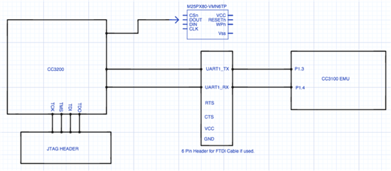
    I have attached a block diagram to how I'm picturing this whole set up on how the cc3200 would be flashed/debugged, just so that I'm fully understanding how to everything is connected together. 

    Because I'm powering the CC3200 using USB power only, I'm assuming that the booster pack would need a separate usb cable for programming am I correct?

    Again, thanks for the help!

    Regards,

    Li-Yen

  • Yang1 said:
    If I were to use an FTDI cable would the RTS and CTS lines be left floating or be connected to a GPIO of the CC3200?

    I am not sure I fully understand this question. You would connect directly to the UARTs as explained in the link I provided. Your diagram looks good. I have not actually done this, so I cannot advise specifics, just the information that has been provided by the CC3100/CC3200 team.

    I've had a quick look into your diagram and it looks fine....I did not however verify everything.

    Yang1 said:
    Because I'm powering the CC3200 using USB power only, I'm assuming that the booster pack would need a separate usb cable for programming am I correct?

    I am confused however as to why you believe you need USB on your custom board? USB would connect to your programmers/emulators, i.e. the CC3100 EMU Boost and the JTAG programmer/debugger (eg. XDS100). But you would use headers as you have shown in your diagram to connect to the board.

    If your question is, how do you power and then program with the CC3100 EMU Boost, then yes this uses a USB cable to perform this task.

    Glenn.

  • Thanks Glen for your responses.

    Sorry if I wasn't clear on my first question.  When I looked online about FTDI cables, there's 6 connection lines. 
    1) TX,

    2) RX,

    3) RTS (Request to send)

    4) CTS (Clear to send)

    5/6) Ground and VCC,

    If I was to use a FTDI cable, I wasn't quite sure if the RTS and CTS lines would be connected to GPIOs on the CC3200 or leave them unconnected. From what I've read online these two lines on FTDI cables are for control flow/handshake signals.

    Again, thanks for your help, and sorry for being so persistent. 

    - Li-Yen

  • I have not done this my self, you have all the same information I have....but I suspect you would not need the RTS and CTS connected, as this is not recommended in the details I provided.....just Tx and Rx....not sure which cable, perhaps a 3.3v one?

    Glenn.

  • Thanks Glenn for all the help!

    :)

  • Hi Li-Yen,

    I've read  somewhere that CTS is pulled up to VCCIO by 200kOhm by default in the ftdi chip. I am not sure what should be done with RTS and CTS in this case though. cc3200 documentation doesn't seem to mention those lines. Let me know if you have any update on this question, it's interesting.

    David

  • Hey David,

    The answer I received from a different forum was, other than the RX & TX lines on a FTDI cable, the GND pin must be connected. Everything else (RTS, CTS, and VCC) can be left floating, unless you want to use the VCC line (5V) to power up your device.

    Hopefully this helps!

    Li-Yen

  • Li-Yen, thanks!

  • Hi Li-Yen,

    Thanks for the update. It will be nice if you can post the link to the other forum here for reference.

    Thanks,
    Sridhar