


I need to receive an OOK modulated signal with the CC1101. The signal is a manchester encoded signal at 650 Baud at 868 MHz.
I am able to receive the signal with the right settings in SmartRF Studio. However, the reception is very unstable. I used the async. RX and Carrier sense signals to determine the signal. The mark/space ratio of the symbols gets fully distorted, making further decoding unable. Sometimes the received RX clips to '1' other times it clips to '0'. It seems the AGC is not able to settle accurate enough.
I followed the design note DN022 for the register settings but even with optimum settings I am still unable to receive a stable signal.
Below some scope images of the transmitted signal (below) and the received signal (above).
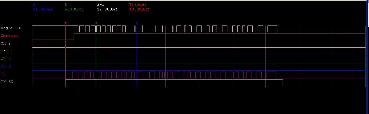

http://e2e.ti.com/cfs-filesystemfile.ashx/__key/CommunityServer-Components-ImageFileViewer/CommunityServer-Discussions-Components-Files-155/3108.sc1.PNG_2D00_1550x0.png
I tried many preferred settings but also very many trial-and-error settings, but I am not able to get a good reception.
Any help on this is well appreciated!
Regards,
Rolf


