This thread has been locked.

If you have a related question, please click the "Ask a related question" button in the top right corner. The newly created question will be automatically linked to this question.

RI-R6C-001A and Tag-it HF Sandard transponders

Other Parts Discussed in Thread: TRF7970A, MSP430G2553, TIDM-NFC-EZ430-MODULE, UNIFLASH, MSP430F2370

I want to use RI-R6C-001A along with Tag-it HF Sandard Transponders inlays.Does anybody has an example software? I cannot undersand how to implement the tag-it transponder protocol in software.I need some starting guidance. 

  • here are some training slides. and once you read through this and get through those steps hit me back and i can give you further guidance. Which MCU are you planning on using?

    8267.HF-I Transceiver.ppt

  • Thank you for sending me the information. I have few questions.

    Can I use high data rate with Tag HF-I transponders Inlays like RI-I11-112A or RI-I11-114A or only low data rate is allowed?

    Are the protocols Tag-it HF and Tag-it HF-I different?

    Does the communication between R1-R6C-001A and RI-I11-112A require Tag-it HF-I (ISO 15693)?

    Should I use FORWARD CCIT, SartValue 0xFFF, I’s compliment to calculate CRC for R1-R6C-001A and R1111-112A communication. Can I get software to calculate it?

    Can I use FM for downlink and uplink communication with R1-R6C-001A and R1111-112A or only AM is allowed (due to RI-I11-112A)?

    What does 1 slot or 16 slots mean and 1 out of 4 or 1 out of 256 means in ISO15693?

    Sould I send the bytes as mentioned in the last line of Page 18?

    For my application I have to place a reader/ writer inside the instrument. This instrument has to use a filter for smoke suction purpose in a medical purpose. I have to place the Tag on the filter to recognize the filter. If the filter inserted is from our company then the instrument will work with this filter otherwise not.The other thing required is the save the used time of the filter on the Tag.

    For this application I thought to use the R1-R6C-001A and RI-I11-112A. Can you tell me some other options with evaluation boards?

    Will it be good and simple to use TRF7970A and RI-I11-112A?

    At the moment I have not planned which microconroller to use as I have to build many oher circuits like TRIAC control for DC motor.

  • 1. both tag data rates are possible and high tag data rate is recommended usually, since when reading out many data blocks it leads to slightly better user experience. People really won't ever perceive any difference on the basic operations like Inventory or Read Single Block. 

    2. Yes - the protocols are different between Tag-It HF and HF-I...HF-I is ISO15693 (that is the I in HF-I), Tag-It HF is discontinued for several years now. It was the protocol we had before we created ISO15693.

    3. The R6C can support - but again, as the older version is discontinued, there is most likely no point in supporting. 

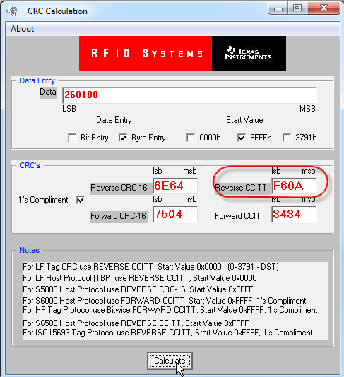
    4. The ISO15693 downlink (reader to tag) uses REVERSE CCITT, start value of 0xFFFF, 1's complement for CRC. For the S6700 (RI-R6C device), using Inventory Command as simple example, there is a command byte, request flags, command and mask. the CRC is calculated on just the request flags, command and mask...so if doing single slot, this would be 0x26, 0x01, 0x00, with a CRC of 0xF60A.  Here is a picture of the calculator i am attaching at the bottom of this post. 

    5. ISO15693 downlink is always ASK. Only the modulation depth can be varied and TI ISO15693 ICs prefer 23% or greater.

    6. Single slot means only one tag is expected in the field. it is indicated to the tag by the reader in the request flags. The sixteen slot inventory is used when many tags are expected in the field and the anti-collision algorithm is a slotted ALOHA, which means that it is a recursive call. that starts with sending the inventory command with a mask of 0x00 and the tags use the lower nibble of the LSByte of their UIDs to respond in a respective timeslot that is controlled by the reader sending 15 subsequent EOF/Slot Marker Commands. This means if the tag ends in a 0, then it will respond to the command itself (first slot), if the tag ends in an F, then it will respond to the last EOF/Slot Marker (16th slot). If there is a collision in a slot (i.e. two tags are present which end in same value) then a collision is generated. The reader firmware has to "remember" that happened, and then finish the round to make sure it gets all the tags present. Then the reader will re-issue the inventory command and increment the mask, which will allow the tags that previously collided on the lower nibble to respond using the upper nibble of the LSByte. If they collide again, the reader has to "remember" that again, and finish the round again, increment the mask and repeat until the collision is arbitrated.

    1 of 4 vs. 1 of 256 data coding are the two methods by which the reader "talks to the tag" - both are PPM.

    1 of 256 is one byte indicated by an 18.88uSec pause within a timeframe of 4.833mSec. Resulting data rate is ~ 1.66kbps.

    1 of 4 is a bit faster...two bits are sent within a 75.52uSec time window (either 00, 01, 10 or 11) and four successive pairs form a byte, and the resulting data rate is 26.48kbps. 

    7. Yes - you have to send the bytes out exactly like page shows. We can provide you screen shots of that if you get stuck. 

    8. Any of the ISO15693 tag form factors are good ones - whatever fits your application the best is what you should use. 

    9. The TRF7970A BoosterPack / MSP-EXP430G2553 combo (we made a soft bundle on the TI eStore) might be best for you to use. The R6C is a good part, but the TRF is much less of a firmware development burden, and it sounds to me like you have alot of other things to work on in your system.  This HW might be a better choice for you. eStore link==> https://estore.ti.com/trf7970a-bndl.aspx, plus we have complete software example already done, too - so you really don't have to learn this protocol unless you want to - (i don't mind explaining it, of course, but the logical reason this hardware/firmware solution exists is for folks exactly in your position) :) 

    Plus you will still have GPIO avaialble to run your triac, for your motor, from the MSP430G2553 MCU. 

    CRC Calculator Tool: 

    4505.CRCCalculator.zip


  • Thanks for your reply.

    If I use the circuit of MSP-EXP430G2 in my project on my own PCB, how can I program the microcontroller MSP430 with the RFID program in a simple way? Do I need an expensive devices to program it or can I program it direclty with a terminal program(like devices which already have bootloader).

    Do I need to compile the RFID example program with CCS or a compiled file is available for loading directly into any MSP430?

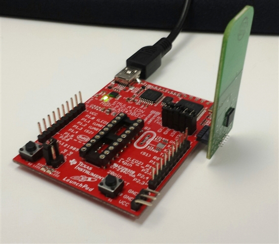
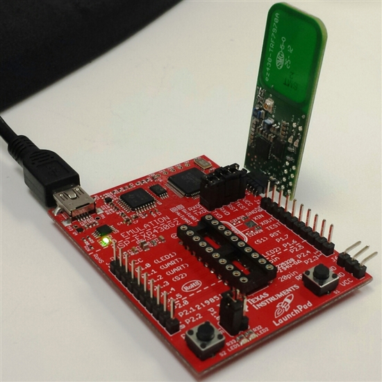
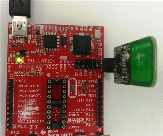
  • if you use the SBW / UART port available on the MSP-EXP430G2 LaunchPad, with the MCU removed from the socket on the LaunchPad (like this, below), you can use it to program and debug the MSP430G2553 on your board.

    This is showing how we program the TI Design ==> http://www.ti.com/tool/TIDM-NFC-EZ430-MODULE, using either CCS (compile, download, debug) or CCS Uniflash (just download)


  • I have bought a TRF7970EVM module.I can communicate with the GUI software from Texas instrument but I cannot receive anything with Docklight terminal program.I can see that it is connected and it sends commands but I do not receive anything.I am using the commnads which appear in the GUI of Texas instrument software like 0108000304FF0000 and 010A0003041001210000.What should I do to receive with the EVM with Docklight? I am using 115200, Parity None, 8 bits and  1 stop bit.

    It appears that the terminal program is sending but not receiving anything

    I cannot understand the following commands

    16:29:57.728 --> 0108000304FF0000                     Where can I find the FF command?
    16:29:57.738 <-- TRF7970A EVM       

    16:30:33.372 --> 0109000304F0000000                 Where can I find the F0 command?
    16:30:33.781 <-- AGC Toggle

    and   

    16:30:33.785 --> 0109000304F1FF0000                Where can I find the F1 command?
    16:30:34.193 <-- AM PM Toggle

    Thre is no AGC Toggle or AM PM toggle command available in application notes.


  • Tahir - 

    0xFF is from host.c file inside the EVM firmware, as is 0xF0 and 0xF1

    a Docklight Project is attached which gets EVM out of standalone mode, then sets protocol and i put some commands in there for example...16 and 1 slot inventory, read single block, read multiple blocks, write single block...

    you can see picture below, too. 

    1307.TRF7970AEVM_ISO15693.7z

  • I am trying o download Uniflash sofware.When I open the zip files I cannot found any seup file(.exe)? I see the following after unzip.I cannot see any seup file.The same thing happens when I download CCS.How can I found seup file.I have tried different zip program

  • check your downloads folder

  • The problem is that I cannot execute the files downloaded in download Folder.The CCS executable file worked when I added .exe at the end but the downloaded files for Uniflash is still not working even when I add .exe at the end.

    Can I also program MSP430F2370(used on TRF7970 EVM) with MSP-EXP430G2 Launch pad as I cannot see TEST/SBWTCK and RST_NMI/SBWTDIO Pins on MSP430F2370 which are present on MSP430G2xx3(used on eZ430-TRF7970 board)?

    I am making a PCB with MSP430F2370 and TRF7970A and I want to program the microcontroller with MSP430G2 Launch Pad.

  • you should redownload then - sounds like it is corrupted - i just downloaded the installer from here ==> http://www.ti.com/tool/uniflash , then run as administrator

    on MSP430F2370, RST pin is Pin38, TCK pin is 37

    http://www.ti.com/lit/ds/symlink/msp430f2370.pdf 

  • can I program MSP430F2370 with  MSP-FET430UIF? Uniflash shows three possibilities TI MSP430 USB1,  TI MSP430 USB2 and  TI MSP430 USB3 which one is to be slelected for MSP-FET430UIF when programming MSP430F2370.

  • with the FET tool and Uniflash, choose TI MSP430 USB1

  • I have downloaded the Software for TRF7970A EVM from TI website.I see two .out files present in this Software.One is TRF7970A_07_25_2011.out and the other is TRF7970A_EVM 1.6 from 10_1_2013.out. What is the difference between the two files and which one is present is the EVM board delivered from Texas insrument? I cannot complie the Software as I have free Version of CCS.The code size is bigger than what free version can compile. 

  • The latest Rev. is 1.6..the code size is (as you say) 19.8kB, so you are right free version of CCS won't do it. 

    Options here (depending on your end goal) would be to get -G2xx LaunchPad and TRF7970A BoosterPack instead or get full version of CCS>

    https://estore.ti.com/trf7970a-bndl.aspx 

  • Tahir - 

    Another thought i had tonight about this was to use the optimization feature in CCS. 

    no opt. ==> 20.772kB Flash Used

    Level 0 ==> 17.538kB Flash used

    Level 1 ==> 16.828kB Flash used

    Level 2 ==> 11.148kB Flash used

    Level 3 ==> 12.240kB Flash used

    Level 4 ==> 11.212kB Flash used

    so it looks like levels 2-4 might then work out for the free version of CCS - can you give that a try? 

  • It works with Level 1 only.

  • Can you please tell me an amplifier to enhance the trasmitted power.I have made some small anntenas on the PCB but the range is not good enough.I do not want to increase the annenna size.

  • for S6700 (RI-R6C-001A) or TRF79xxA?

    how big is the transponder? what is the protocol? what distance are you looking for? did you try to retune the antenna already? what is the end application? 

  • I am using TRF7970A.I am using the TRF7970A Evaluation board sofware.The transponder is  MINI_TAGst 8.5(datasheet attached).The Evaluation module does not work in standalone mode with this transponder.It works with docklight but only with 1-Slot but not with 16 Slot.The protocol is ISO15693.

    The Evaluation module TRF7970A works with Transponders obtained with the EVM board in all cases.

    I have tuned small anntena (14mm inner diagonal) on my board.I can recognize  this tag up to a distane of 7mm.The Maximum Signal strength obtained with docklight is 47h [0030260100000000,47]. 

    The end application is to recognize that the plug is inserted into the Instrument socket(Tag sits in the plug). 


    3000.MINI-TAGst85-01.pdf

  • Tahir - 

    i emailed this company about their tag - their apps engineer told me some of their tags do not support ISO15693 completely - which is OK with the TRF79xx parts - but we need to know the commands to send, mod depth setting, etc - so they asked me to ask you which exact part number you are wanting to use - so they can provide the correct technical data sheet which will then allow us to tell us/you how to handle it. 

  • We are using two type of MINI-TAGst 8.5 tags mentioned at the end of data sheet which I sent to you. 

    Type 1 = 15.36.342.00

    Type 2 = 15.54.342.00 

  • Tahir - 

    the guy from microsensys told me that 

    Type 1 = 15.36.342.00 is compliant with ISO15693-3

    Type 2 = 15.54.342.00 is compliant with ISO15693-2

    i asked him full data sheet / user guide to see the commands these tags support, mod depth and any other special things to know about and so now i am waiting to hear back again

  • Thanks for your reply.Please guide me when you get the answer.

  • Tahir - 

    these guys refused to give me any more info about these tags, so i could continue to help you out. they claim these tags were made for a specific customer and therefore are under NDA - so not sure why they offer them to broad market - anyway - to solve your issue once and for all - if you are interested in finding another tag vendor in the same size range, who uses 100% ISO15693 compliant silicon (including TI's offerings), i can help there.

    two companies that come to mind are SAG and Syrma.

    Just tell either one of them (or both) I sent you. Both of them can/do make a tag the size you need.

    SAG ==> http://www.sag.com.tw/index.php?_Page=product&mode=list&cid=4&SetLang=en-us 

    Syrma ==> http://www.syrma-rfid.com/tagsandinlays.html 

    For RFID Products contact Paul Dahl at:
    Phone: +1 952-955-7525 
    E-mail:  

  • Is it possible to write to a TAG with Write Single Block Command (0x21) when the block size is 8 bytes using TRF7970 EVM and its software? I have asked the TAG manufacturer Microsensys they have told me that that the Tag can be written by considering the block size as 8 bytes.The Tags which I used from Texas instruments have 4 bytes in a block.

  • the format of the command itself makes no restriction on the block length - you just need to input flags, command, block # (to write) and the data to write

    and

    the TRF79xxA itself does not check any length, so there will be no issue using it, as long as you format the flags +command + block  # + data correctly.   

  • I want to implement the SPI with SS mode to communicate with the TRF7970A.

    The application note SLOA140-April2009 which describes how to use SPI interface with TRF7690 talks about changing the clock polarity.Do I need to change the clock polarity with TRF7970A also for write and read. Which baud rate do you recommend? It looks that the EVM board TRF7970A software does not change clock polarity.

    Do you have any application note for SPI communication with TRF7970A or SLOA140-April2009.Can you send some photos with SPI Signal to commuincate with TRF7970A? 

  • no clock polarity change inside the MCU is required between writes and reads to the TRF7970A IC when using SPI w/SS

    http://www.ti.com/lit/an/sloa159/sloa159.pdf (see section 7.5 here)

    i have enabled only ISO15693 in the example attached here, which is taken from MSP430G2553 driving TRF7970A (LaunchPad + BoosterPack combo)

    6443.TRF7970A_ISO15693_G2553_BoosterPack_Example.zip

    you can download free viewer here ==> http://support.saleae.com/hc/en-us/articles/201589175-Logic-1-1-31-Beta

  • Hello Josch,

    I´m implementig a RI-R6C Tranceiver on a circuit. My problem is that I cannot make the crystal to oscillate. I have followed the example circuit in the Datasheet of this IC (SCBU030 – July 2005). Do you now what could be the problem. Do I need to use a specific command sent from uC to the IC? Is it set to power down mode for default?

    Best regards,

    Victor
  • your wiring is probably amiss - do you have your schematic?
  •  Yes, I have it.

  • hey - you may want to beep out a bareboard - i see you have some names that are incorrect - in case the nets got connected where they don't belong

    also, your impedance match is off and then for the crystal issue, check your load caps and your rise time. 

    for example: 

    if you see this kind of stuff on your crystal after you check/fix your board, slow the rise time down on the power supply

    should end up looking like this

    if you need more i did a report on this for a customer - can't give you that, but i can answer questions.

  • also - here is the training on this IC

    HF-I_Transceiver.pdf

  • Ok,

    First, thanks for your help, I still have some questions:

    - What do you mean with worng names? If you mean those of the RI-R6C chip, I used another chip in Eagle which had the same casing.

    - I can see that the impedance matching circuit you have is a little bit different as the one I have, is mine outdated?

    My real issue is that I have no response of the crystal, it simply have no oscillation. Is the RI-R6C in a Idle Mode so the crystall cannot vibrate?

    Or it must start working when connected to power?

    Thank you for your help J

  • see page 3 of the PPT for the pinout names 

    the impedance matching you have there was done by marketing - never put into production

    the one i gave you was done by engineering and was put into production - and is the original match that was introduced with the IC

    the crystal should come up on power up as i put in the first response - if that is not happening, its time to get the multi-meter out and check your board and solder

    connections (see slide 12 in the training)

  • Ok, thank you for your advice, I have now done the connections as you said.


    I have a last question, the clock signal on pin 8 should come out at all times? or do I need to send a command to the RI-R6C?

    Thank you for your help.

  • Victor - 

    Pin 8 is the buffered crystal output pin, so yes, as long as the crystal is running, the buffered version of it will be on that pin.

  • Josh-

    Now I have another question, does the RI-R6C can be controlled by a normal SPI module? Because I´ve been trying to send some bytes. And also because it

    it says some specification of the protocol such as maintaining the SCLK at high level and then a DIN low-to-high.

  • Victor -

    this is 3 wire SPI

    DIN, DOUT and bi-directional SCLOCK, with an M_ERR pin as well. 

    pls. see attached logic captures for example.

    LOWBAUD_INVENTORY.pdf

    HIGHBAUD_INVENTORY.pdf

  • Josh-

    Hi, again

    I´ve been trying to get the Buffered Clock on pin 8. In fact I can read a clock signal with my oscilloscope, problem is that my original amplitude is 4.5V and the output ov pin 8 is 45mV. Also the signal is very noisy. Can this be solved? How can I read a much powerful signal?

    Thank you for your advice.

    BR,

    Victor

  • could be your scope probe, your ground, or your wiring

    if the probe works for measuring correct levels of other signals, then go for troubleshooting the wiring on your board. 

    send schematic and pix if you cannot figure it out.

  • OK, I´ve tried and no answer yet from the RI-R6C

    I had to make my own communication programm, because I´m using a dsPIC33F (what I had in hand) as controller.

    Now I send the clock and data as requested in the protocol from the ri-r6c and it simply doesn´t answer.

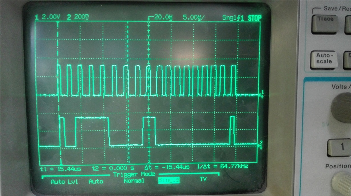
    Here are some photos I took from my scope.

    This is the read sequence (0x71 and then read): I only have two probes, but I run it twice and the answer from ri-r6c was nothing, also on the m_err pin, it simply does not do something.

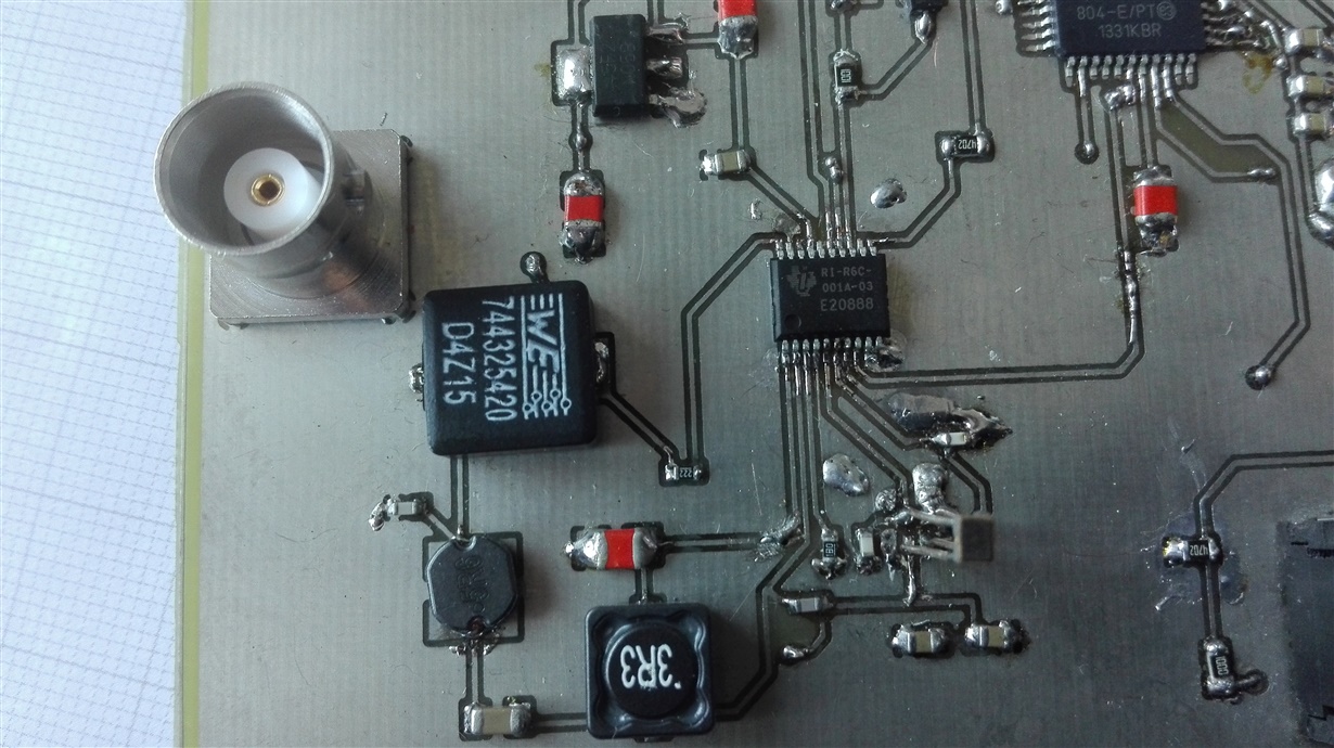
    Now here I also attach my schematics and a photo from the board.

    Photo

    What do you recommend?

    I also tested all the connections, the only thing I do not have the same as you said is the matching circuit, but until now it is not important, because I only want to stablish communication between my two IC and the ground planes.

    Note. I had a level changer, but didn´t work good, so now i have directly connected the uC outputs to the ri-r6c.

    Note 2. The schematic ri-r6c -> on my schematic the image of the RI-R6C is another IC, the only thing that matterst there is that it had the same footprint so I could use it on my board, so the names on each pin of the schematic "RI-R6C" will NOT be the same as they are in the real RI-R6C

  • Victor -

    the crystal is running now?

    then check the attached .c file which was written for the S6700 part

    also, just FYI - you need to use inductors which are for 13.56MHz, not power supply ones. (at least, you will have much better results if you choose parts that are for the band) and the layout could use some cleanup as well - things are really spread out here and from the picture, i would check your soldering, too - to make sure you don't have cold joints or opens/shorts somewhere.

    hfasic.c
    #define HF_ASIC_GLOBALS
    #include "includes.h"
    
    /******************************************************************************
     *
     * File Name: HFASIC.c
     * Copyright Texas Instruments, Inc. 2003. All rights reserved
     *
     * Description:
     *    This file contains the routines that implement the basic HF ASIC
     *    interface.
     *
     * Revision History:
     *
     *----------+----------+---------------+---------------------------------------
     *          | Version  |               |
     *   Date   | Modified |    Author     | Description
     *----------+----------+---------------+---------------------------------------
     *          |          |               |
     *----------+----------+---------------+---------------------------------------
     *****************************************************************************/
    
    
    // Added the following conditional to allow the released library files to compile with no warnings
    // For internal use the DEBUG_MODE can be added into the Project files globals and have the warnings appear
    #ifndef DEBUG_MODE
      #pragma warn-       // Disable warnings
    #endif
    
    //static BOOLEAN setThreshold = FALSE;
    
    //uchar hfAsicTimeout = 1;
    
    #ifdef HAVE_14443_B
      extern INT16U *T1A_ptr;
    #endif
    
    static BOOLEAN AsicReplyCriteria(void)
    {
      return ( ( SCLOCK_High() ) && ( DOUT_High() ) );
      //return FALSE;
    }
    
    // isLsbFirst shall be set TRUE if bits are collected LS bit first.
    static unsigned char Local_ASIC_Receive_Bits(BOOLEAN isLsbFirst, uchar fwi, uchar wtxm, INT16U initByteCount, uchar initBitCount)
    {
      unsigned int delay_count;
      unsigned char ES2_Detected = FALSE;
      register uchar data_in;
      register uchar *pChar;
      register uchar mask;
    
      HF_ASIC.rcvdBytes = initByteCount;
      HF_ASIC.rcvdXtraBits = initBitCount;
    
      if ( (initByteCount == 0) && (initBitCount == 0) )
        HF_ASIC.Buffer[0] = 0;
    
    
      // Wait until SCLOCK goes high and then wait until DOUT also goes high.
      // When this happens, event S2 has occurred.
      data_in = FrameWaitTimer(fwi, wtxm, AsicReplyCriteria );  // 2.5 us
    
      // If there was an error (i.e. ERROR_TOKEN_NOT_PRESENT or ERROR_HF_ASIC_ABORTED)...
      if (data_in != ERROR_NONE)
        return data_in;           // Return error status
    
      data_in = Get_DOUT();
    
      // S2 Detected. Now wait for S2 completion => SCLOCK goes low.
      delay_count = 500;                    // Delay
      if (data_in != 0)
      {
        while (1)
        {
          if (!SCLOCK_High())
            break;
    
          // If DOUT goes low during SCLOCK pulse.....
          if ( !DOUT_High() )
          {
            // If SCLOCK is still high...
            if (SCLOCK_High())
              ES2_Detected = TRUE;
          }
    
          if (!SCLOCK_High())
            break;
    
          if (M_ERR_High())
            return ERROR_COLLISION_DETECT;
    
          if (!SCLOCK_High())
            break;
    
          // If DOUT goes low during SCLOCK pulse.....
          if ( (!DOUT_High()) )
          {
            // If SCLOCK is still high...
            if (SCLOCK_High())
              ES2_Detected = TRUE;
          }
    
          if (!SCLOCK_High())
            break;
    
          delay_count--;
    
          if (delay_count == 0)
            return ERROR_HF_ASIC_RECEIVE_TIMEOUT;
        }
      }
      else
      {
        while (1)
        {
          if (!SCLOCK_High())
            break;
    
          if (M_ERR_High())
            return ERROR_COLLISION_DETECT;
    
          delay_count--;
    
          if (!SCLOCK_High())
            break;
    
          if (delay_count == 0)
            return ERROR_HF_ASIC_RECEIVE_TIMEOUT;
        }
      }
    
      // Start receiving data now.
      while ((!ES2_Detected) && (!Abort_Module()))
      {
        if (M_ERR_High())
          return ERROR_COLLISION_DETECT;
    
        pChar = (HF_ASIC.Buffer + HF_ASIC.rcvdBytes);
        pChar[1] = 0;
    
        mask = 1 << ( (isLsbFirst) ? HF_ASIC.rcvdXtraBits : (7 - HF_ASIC.rcvdXtraBits) );
    
        // Wait until SCLOCK goes high and then collect data or check for ES2
        delay_count = 1500;                  // Delay
        while (1)
        {
          if (SCLOCK_High())
            break;
          if (delay_count == 0)
            return ERROR_HF_ASIC_RECEIVE_TIMEOUT;
          if (SCLOCK_High())
            break;
          if (M_ERR_High())
            return ERROR_COLLISION_DETECT;
          delay_count--;
        }
    
        // Store incoming bit into the receive buffer
        data_in = Get_DOUT();
    
        if (data_in != 0)
          *pChar |= mask;
    
        HF_ASIC.rcvdXtraBits = (HF_ASIC.rcvdXtraBits + 1) & 0x07;
    
        if (HF_ASIC.rcvdXtraBits == 0)
          HF_ASIC.rcvdBytes++;
    
        if (M_ERR_High())
          return ERROR_COLLISION_DETECT;
    
        delay_count = 2000;
        if (data_in != 0)
        {
          while (1)
          {
            if (!SCLOCK_High())
              break;
    
            // If DOUT goes low during SCLOCK pulse.....
            if ( !DOUT_High() )
            {
              // If SCLOCK is still high...
              if (SCLOCK_High())
                ES2_Detected = TRUE;
            }
    
            if (!SCLOCK_High())
              break;
    
            if (M_ERR_High())
              return ERROR_COLLISION_DETECT;
    
            if (!SCLOCK_High())
              break;
    
            // If DOUT goes low during SCLOCK pulse.....
            if ( (!DOUT_High()) )
            {
              // If SCLOCK is still high...
              if (SCLOCK_High())
                ES2_Detected = TRUE;
            }
    
            if (!SCLOCK_High())
              break;
    
            delay_count--;
    
            if (delay_count == 0)
              return ERROR_HF_ASIC_RECEIVE_TIMEOUT;
          }
        }
        else
        {
          while (1)
          {
            if (!SCLOCK_High())
              break;
    
            if (M_ERR_High())
              return ERROR_COLLISION_DETECT;
    
            delay_count--;
    
            if (!SCLOCK_High())
              break;
    
            if (delay_count == 0)
              return ERROR_HF_ASIC_RECEIVE_TIMEOUT;
          }
        }
      }
    
      if (Abort_Module())
        return ERROR_HF_ASIC_ABORTED;
    
      return ERROR_NONE;
    } // End of Local_ASIC_Receive_Bits()
    
    
    /******************************************************************************
     * Function Name: HF_ASIC_Send_S1()
     *
     * Description:
     *    This function will send a "S1" according to the definition in RI-R6C-001A
     *   HF Reader System Series 6000, S6700 Multiprotocol transceiver IC, reference
     *   guide, pages 18 and 19.
     *
     * Parameters:
     *    none
     *
     * Returns:
     *    none
     *
     * Revision History:
     *----------+----------+---------------+---------------------------------------
     *          | Version  |               |
     *   Date   | Modified |    Author     | Description
     *----------+----------+---------------+---------------------------------------
     *          |          |               |
     *----------+----------+---------------+---------------------------------------
     *****************************************************************************/
    void HF_ASIC_Send_S1(void)
    {
      Clear_SCLOCK();                       // SCLOCK = 0
      Clear_DIN();                          // DIN = 0
    
      // Set SCLOCK and wait 5 cycles - at least 300 ns delay
      Set_SCLOCK();                         // SCLOCK = 1
      #asm("NOP");
      #asm("NOP");
      #asm("NOP");
      #asm("NOP");
      #asm("NOP");
    
      // Set DIN and wait 5 cycles - at least 300 ns delay
      Set_DIN();                            // DIN = 1
      #asm("NOP");
      #asm("NOP");
      #asm("NOP");
      #asm("NOP");
      #asm("NOP");
    } // End of HF_ASIC_Send_S1()
    
    
    /******************************************************************************
     * Function Name: HF_ASIC_Send_ES1()
     *
     * Description:
     *    This function will send a "ES1" according to the definition in RI-R6C-001A
     *   HF Reader System Series 6000, S6700 Multiprotocol transceiver IC, reference
     *   guide, pages 18 and 19.
     *
     * Parameters:
     *    none
     *
     * Returns:
     *    none
     *
     * Revision History:
     *----------+----------+---------------+---------------------------------------
     *          | Version  |               |
     *   Date   | Modified |    Author     | Description
     *----------+----------+---------------+---------------------------------------
     *          |          |               |
     *----------+----------+---------------+---------------------------------------
     *****************************************************************************/
    void HF_ASIC_Send_ES1(void)
    {
      Clear_SCLOCK();                       // SCLOCK = 0
      Set_DIN();                            // DIN = 1
    
      // Set SCLOCK and wait 5 cycles - at least 300 ns delay
      Set_SCLOCK();                         // SCLOCK = 1
      #asm("NOP");
      #asm("NOP");
      #asm("NOP");
      #asm("NOP");
      #asm("NOP");
    
      // Set DIN and wait 5 cycles - at least 300 ns delay
      Clear_DIN();                            // DIN = 0
      #asm("NOP");
      #asm("NOP");
      #asm("NOP");
      #asm("NOP");
      #asm("NOP");
      Clear_SCLOCK();                       // SCLOCK = 0
    } // End of HF_ASIC_Send_ES1()
    
    
    /******************************************************************************
     * Function Name: HF_ASIC_Send_Bit()
     *
     * Description:
     *    This function will send a bit according to the definition in RI-R6C-001A
     *   HF Reader System Series 6000, S6700 Multiprotocol transceiver IC, reference
     *   guide, pages 18 and 19.
     *
     * Parameters:
     *    uchar   bit_val   indicates whether a 0 or 1 should be sent
     *
     * Returns:
     *    none
     *
     * Revision History:
     *----------+----------+---------------+---------------------------------------
     *          | Version  |               |
     *   Date   | Modified |    Author     | Description
     *----------+----------+---------------+---------------------------------------
     *          |          |               |
     *----------+----------+---------------+---------------------------------------
     *****************************************************************************/
    void HF_ASIC_Send_Bit(unsigned char bit_val)
    {
    	INT16U loop_cnt;
    	
      // Wait until DOUT goes low - DOUT low means FIFO is not full
     // while (DOUT_High()) { }
    	loop_cnt = 0;
    	while(1)
    	{
         if (!DOUT_High())
           break;
         loop_cnt++;
         // Check for condition where the HFASIC locks up with DOUT high
         // Just go on and hope for the best
         if( loop_cnt == 0xFFFF)
           break; 
    	}
    
      Clear_SCLOCK();                       // SCLOCK = 0
      #asm("NOP");
      #asm("NOP");
      #asm("NOP");
      #asm("NOP");
    
      if (bit_val)
      {
        // Send a 1 bit
        Set_DIN();                            // DIN = 1
      }
      else
      {
        // Send a 0 bit
        Clear_DIN();                          // DIN = 0
      }
      #asm("NOP");
      #asm("NOP");
      #asm("NOP");
      #asm("NOP");
    
      // Set SCLOCK and wait 10 cycles - at least 600 ns delay
      Set_SCLOCK();                         // SCLOCK = 1
      #asm("NOP");
      #asm("NOP");
      #asm("NOP");
      #asm("NOP");
      #asm("NOP");
      #asm("NOP");
      #asm("NOP");
      #asm("NOP");
      #asm("NOP");
      Clear_SCLOCK();                       // SCLOCK = 0
    } // End of HF_ASIC_Send_Bit()
    
    
    /******************************************************************************
     * Function Name: HF_ASIC_Transmitter_On()
     *
     * Description:
     *    This function will turn on the transmitter (carrier frequency 13.56 MHz)
     *  according to the definition in RI-R6C-001A HF Reader System Series 6000,
     *  S6700 Multiprotocol transceiver IC, reference guide, page 20.
     *
     * Parameters:
     *    none
     *
     * Returns:
     *    none
     *
     * Revision History:
     *----------+----------+---------------+---------------------------------------
     *          | Version  |               |
     *   Date   | Modified |    Author     | Description
     *----------+----------+---------------+---------------------------------------
     *          |          |               |
     *----------+----------+---------------+---------------------------------------
     *****************************************************************************/
    void HF_ASIC_Transmitter_On(void)
    {
      HF_ASIC_Send_S1();
      HF_ASIC_Send_Bit(1);
      HF_ASIC_Send_ES1();
      hfAsicXmitState = 1;
    } // End of HF_ASIC_Transmitter_On()
    
    
    /******************************************************************************
     * Function Name: HF_ASIC_Transmitter_Off()
     *
     * Description:
     *    This function will turn off the transmitter (carrier frequency 13.56 MHz)
     *  according to the definition in RI-R6C-001A HF Reader System Series 6000,
     *  S6700 Multiprotocol transceiver IC, reference guide, page 20. The sequence
     *  to turn off transmitter is S1, 1, ES1 where the 1 is a bit not a byte.
     *
     * Parameters:
     *    none
     *
     * Returns:
     *    none
     *
     * Revision History:
     *----------+----------+---------------+---------------------------------------
     *          | Version  |               |
     *   Date   | Modified |    Author     | Description
     *----------+----------+---------------+---------------------------------------
     *          |          |               |
     *----------+----------+---------------+---------------------------------------
     *****************************************************************************/
     void HF_ASIC_Transmitter_Off(void)
    {
      Clear_SCLOCK();                       // SCLOCK = 0
      Clear_DIN();                          // DIN = 0
    
      // Set SCLOCK and wait 5 cycles - at least 300 ns delay
      Set_SCLOCK();                         // SCLOCK = 1
      #asm("NOP");
      #asm("NOP");
      #asm("NOP");
      #asm("NOP");
      #asm("NOP");
    
      // Set DIN and wait 5 cycles - at least 300 ns delay
      Set_DIN();                            // DIN = 1
      #asm("NOP");
      #asm("NOP");
      #asm("NOP");
      #asm("NOP");
      #asm("NOP");
    
      // Clear DIN and wait 5 cycles - at least 300 ns delay
      Clear_DIN();                            // DIN = 0
      #asm("NOP");
      #asm("NOP");
      #asm("NOP");
      #asm("NOP");
      #asm("NOP");
      Clear_SCLOCK();                       // SCLOCK = 0
      hfAsicXmitState = 0;
    } // End of HF_ASIC_Transmitter_Off()
    
    
    /******************************************************************************
     * Function Name: HF_ASIC_Send_TRAN1()
     *
     * Description:
     *    This function will send a TRAN1 sequence to the HF ASIC
     *  according to the definition in RI-R6C-001A HF Reader System Series 6000,
     *  S6700 Multiprotocol transceiver IC, reference guide, page 26.
     *
     * Parameters:
     *    none
     *
     * Returns:
     *    none
     *
     * Revision History:
     *----------+----------+---------------+---------------------------------------
     *          | Version  |               |
     *   Date   | Modified |    Author     | Description
     *----------+----------+---------------+---------------------------------------
     *          |          |               |
     *----------+----------+---------------+---------------------------------------
     *****************************************************************************/
     void HF_ASIC_Send_TRAN1(void)
    {
      Clear_SCLOCK();                       // SCLOCK = 0
      Clear_DIN();                          // DIN = 0
    
      // Set DIN and wait 5 cycles - at least 600 ns delay
      Set_DIN();                            // DIN = 1
      #asm("NOP");
      #asm("NOP");
      #asm("NOP");
      #asm("NOP");
      #asm("NOP");
      #asm("NOP");
      #asm("NOP");
      #asm("NOP");
      #asm("NOP");
    
      // Clear DIN and wait 5 cycles - at least 600 ns delay
      Clear_DIN();                            // DIN = 0
      #asm("NOP");
      #asm("NOP");
      #asm("NOP");
      #asm("NOP");
      #asm("NOP");
      #asm("NOP");
      #asm("NOP");
      #asm("NOP");
      #asm("NOP");
      Make_SCLOCK_Input();
    
      Set_DIN();                            // DIN = 1
    
    } // End of HF_ASIC_Send_TRAN1()
    
    
    /******************************************************************************
     * Function Name: HF_ASIC_Send_TRAN2()
     *
     * Description:
     *    This function will send a TRAN2 sequence to the HF ASIC
     *  according to the definition in RI-R6C-001A HF Reader System Series 6000,
     *  S6700 Multiprotocol transceiver IC, reference guide, page 27.
     *
     * Parameters:
     *    none
     *
     * Returns:
     *    none
     *
     * Revision History:
     *----------+----------+---------------+---------------------------------------
     *          | Version  |               |
     *   Date   | Modified |    Author     | Description
     *----------+----------+---------------+---------------------------------------
     *          |          |               |
     *----------+----------+---------------+---------------------------------------
     *****************************************************************************/
    void HF_ASIC_Send_TRAN2(void)
    {
      // Clear DIN and wait 5 cycles - at least 300 ns delay
      Clear_DIN();                          // DIN = 0
      #asm("NOP");
      #asm("NOP");
      #asm("NOP");
      #asm("NOP");
      #asm("NOP");
      // Wait until SCLOCK gies low
      while (SCLOCK_High()) {}
    
      // Set DIN and wait 9 cycles - at least 600 ns delay
      Set_DIN();                            // DIN = 1
      #asm("NOP");
      #asm("NOP");
      #asm("NOP");
      #asm("NOP");
      #asm("NOP");
      #asm("NOP");
      #asm("NOP");
      #asm("NOP");
      #asm("NOP");
    
      // Clear DIN and wait 9 cycles - at least 600 ns delay
      Clear_DIN();                            // DIN = 0
      #asm("NOP");
      #asm("NOP");
      #asm("NOP");
      #asm("NOP");
      #asm("NOP");
      #asm("NOP");
      #asm("NOP");
      #asm("NOP");
      #asm("NOP");
      Make_SCLOCK_Output();
    
    //  Set_DIN();                            // DIN = 1
    
    } // End of HF_ASIC_Send_TRAN2()
    
    
    /******************************************************************************
     * Function Name: HF_ASIC_Read_Bit()
     *
     * Description:
     *    This function will read a bit from the HF ASIC 8-bit FIFO
     *  according to the definition in RI-R6C-001A HF Reader System Series 6000,
     *  S6700 Multiprotocol transceiver IC, reference guide, pages 22, 24 and 25.
     *  This can only be used in the register mode and not in one of the defined
     *  modes or the direct mode (page 19).
     *
     * Parameters:
     *    none
     *
     * Returns:
     *    uchar   0 or a 1 depending on the bit read from the HF ASIC interface.
     *
     * Revision History:
     *----------+----------+---------------+---------------------------------------
     *          | Version  |               |
     *   Date   | Modified |    Author     | Description
     *----------+----------+---------------+---------------------------------------
     *          |          |               |
     *----------+----------+---------------+---------------------------------------
     *****************************************************************************/
    unsigned char HF_ASIC_Read_Bit(void)
    {
      unsigned char rcv_data = 0;
    
      Clear_SCLOCK();                       // SCLOCK = 0
      Clear_DIN();                          // DIN = 0
      #asm("NOP");
      #asm("NOP");
      #asm("NOP");
      #asm("NOP");
      #asm("NOP");
    
      // Set SCLOCK and wait 1 cycle - at least 74 ns delay
      Set_SCLOCK();                         // SCLOCK = 1
      #asm("NOP");
    
      // Get the value of DIN
      rcv_data = Get_DOUT();
    
      // Wait 5 cycles and clear SCLOCK
      #asm("NOP");
      #asm("NOP");
      #asm("NOP");
      #asm("NOP");
      #asm("NOP");
      Clear_SCLOCK();                       // SCLOCK = 0
    
      return rcv_data;
    } // End of HF_ASIC_Read_Bit()
    
    
    /******************************************************************************
     * Function Name: HF_ASIC_Receive_Bits()
     *
     * Description:
     *    This function will read a bit from the HF ASIC 8-bit FIFO
     *  according to the definition in RI-R6C-001A HF Reader System Series 6000,
     *  S6700 Multiprotocol transceiver IC, reference guide, pages 22, 24 and 25.
     *  This can not be used in the register mode or the direct mode. This can be
     *  used in one of the defined modes (page 19, table 5 bit values 001 through
     *  100). This detects manchestor decoder error.
     *
     * Parameters:
     *    BOOLEAN   isLsbFirst  TRUE if bits are to be collected lsb first
     *    uchar     fwi         Frame Wait Integer (per ISO14443 standard)
     *    uchar     wtxm        Wait Time eXtension Multiplier (per ISO14443 standard)
     *
     * Returns:
     *    uchar   Error code. Received data shall be stored in HF_ASIC.Buffer[].
     *
     * Revision History:
     *----------+----------+---------------+---------------------------------------
     *          | Version  |               |
     *   Date   | Modified |    Author     | Description
     *----------+----------+---------------+---------------------------------------
     *          |          |               |
     *----------+----------+---------------+---------------------------------------
     *****************************************************************************/
    unsigned char HF_ASIC_Receive_Bits(BOOLEAN isLsbFirst, uchar fwi, uchar wtxm)
    {
      unsigned char retVal;
      INT_DISABLE(TIMR0_COMP);
    
      retVal = Local_ASIC_Receive_Bits(isLsbFirst, fwi, wtxm, 0, 0);
    
      INT_ENABLE(TIMR0_COMP);
    
      return (retVal);
    
    } // End of HF_ASIC_Receive_Bits()


    /******************************************************************************
     * Function Name: HF_ASIC_Write()
     *
     * Description:
     *    This function will send data_len bytes to the HF ASIC 8-bit FIFO
     *  according to the definition in RI-R6C-001A HF Reader System Series 6000,
     *  S6700 Multiprotocol transceiver IC, reference guide. This is the main
     *  portal for the HF ASIC interface. The command byte (argument cmd) will
     *  indicate the mode in which the data should be sent and also the actions.
     *
     * Parameters:
     *    uchar   cmd       The command byte of the HF ASIC interface protocol.
     *    uchar   data_len  #bytes to be sent.
     *    uchar*  data_ptr  pointer to the data to be sent.
     *    uchar   fwi       Frame Wait Integer (per ISO14443 standard)
     *    uchar   wtxm      Wait Time eXtension Multiplier (per ISO14443 standard)
     *
     * Returns:
     *    uchar   Error code.
     *
     * Revision History:
     *----------+----------+---------------+---------------------------------------
     *          | Version  |               |
     *   Date   | Modified |    Author     | Description
     *----------+----------+---------------+---------------------------------------
     *          |          |               |
     *----------+----------+---------------+---------------------------------------
     *****************************************************************************/
    unsigned char HF_ASIC_Write(uchar cmd,
                                uchar data_len,
                                uchar *data_ptr,
                                uchar fwi,
                                uchar wtxm)
    {
      unsigned char return_value;
    
      if ((REGISTER_MODE & cmd) == REGISTER_MODE)
      {
        // Handle register mode communication
        return_value = Handle_Tag_Comm(cmd, ( ((INT16U)data_len) << 3 ), data_ptr, fwi, wtxm, TRUE, HF_ASIC_FRAME_DEFAULT);
      }
      else if (((CONFIG_MODE & cmd) != CONFIG_MODE) &&
                ((CONFIG_MODE & cmd) <= ISO14443_A_MODE))
      {
        // Normal mode communication with HF ASIC in-built modes
        #asm("CLC");               // Insert opcode to clear the carry bit.
        switch (cmd & MODE_MASK)
        {
            case TAG_IT_MODE :
            case ISO15693_1OUT4_MODE :
            case ISO15693_1OUT256_MODE :
            case ISO14443_A_MODE :
              return_value = Handle_Tag_Comm(cmd, ( ((INT16U)data_len) << 3 ), data_ptr, fwi, wtxm, TRUE, HF_ASIC_FRAME_DEFAULT);
              break;
    
            case DIRECT_MODE :
    #ifdef HAVE_14443_B
              return_value = Handle_Direct_Mode(cmd, data_len, data_ptr, fwi, wtxm);
    #else
              return_value = ERROR_INVALID_RF_FORMAT;
    #endif
              break;
        }
      }
      else if ((CONFIG_MODE & cmd) == CONFIG_MODE)
      {
        #asm("CLC");               // Insert opcode to clear the carry bit.
        switch (cmd & MODE_MASK)
        {
          case READ_CONFIG_REGISTER :
            return_value = Handle_Read_Reg(cmd, data_len, data_ptr);
            break;
    
          case POWER_DOWN :
            return_value = Handle_Power_Down(cmd, data_len, data_ptr);
            break;
    
          default :
            return_value = Handle_Write_Reg(cmd, data_len, data_ptr);
            break;
        }
      }
    
      return return_value;
    } // End of HF_ASIC_Write()
    
    
    /******************************************************************************
     * Function Name: Handle_Tag_Comm()
     *
     * Description:
     *    This function will send num_bits bits to the RF interface
     *  according to the definition in RI-R6C-001A HF Reader System Series 6000,
     *  S6700 Multiprotocol transceiver IC, reference guide. This is the main
     *  portal for the RF interface. The command byte (argument cmd) will
     *  indicate the mode in which the data should be sent and also the actions.
     *
     * Parameters:
     *    uchar   cmd         The command byte of the HF ASIC interface protocol.
     *    INT16U  num_bits    #bits to be sent.
     *    uchar*  data_ptr    pointer to the data to be sent.
     *    uchar   fwi         Frame Wait Integer (per ISO14443 standard)
     *    uchar   wtxm        Wait Time eXtension Multiplier (per ISO14443 standard)
     *    BOOLEAN isLsbFirst  TRUE if bits are to be sent least-significant bit 1st
     *    BOOLEAN frameType   Used to request ISO14443A parity and split bytes
     *
     *  Bit oriented frame has no CRC but has parity bit for each byte. It is
     *  described in detail in ISO14443A - 3 spec. The HF_ASIC.rcvdXtraBits value
     *  returned is a special case and it reflects the number of bits in data_ptr
     *  array that can be sent with an anticollision packet without collision.
     *  HF_ASIC.rcvdBytes contents are meaningless for bit oriented frame.
     *
     * Returns:
     *    uchar   Error code.
     *
     * Revision History:
     *----------+----------+---------------+---------------------------------------
     *          | Version  |               |
     *   Date   | Modified |    Author     | Description
     *----------+----------+---------------+---------------------------------------
     *          |          |               |
     *----------+----------+---------------+---------------------------------------
     *****************************************************************************/
    unsigned char Handle_Tag_Comm(uchar cmd,
                                  INT16U num_bits,
                                  uchar *data_ptr,
                                  uchar fwi,
                                  uchar wtxm,
                                  BOOLEAN isLsbFirst,
                                  BOOLEAN FrameRetType)
    {
      INT16U srcIdx, destIdx;
      uchar srcMsk, destMsk;
      register uchar indx;
    
      uchar temp, temp1, parity;
      INT16U response_location;
      INT16U count, num_bytes;
      uchar ret_val;
      uchar frameType;
    
      ret_val = ERROR_NONE;
      frameType = FrameRetType;
    
      // Send S1 to start with.
      HF_ASIC_Send_S1();
    
      // Send command
      if ((REGISTER_MODE & cmd) == REGISTER_MODE)
      {
        // Register mode - Command is just a bit. Send a '1' bit.
        HF_ASIC_Send_Bit(1);
      }
      else
      {
        // Normal mode - send the command byte.
        temp = cmd;
        for (indx = 0; indx < 8; indx++)
        {
          HF_ASIC_Send_Bit((temp & 0x80) >> 7);
          temp <<= 1;
        }
      }
    
      num_bytes = (num_bits >> 3);
    
      // Send data
      for (count = 0; (count < num_bytes); count++)
      {
        parity = 1;
        temp = data_ptr[count];
    
        for (indx = 0; indx < 8; indx++)
        {
          if (isLsbFirst)
          {
            if (temp & 0x01)
              parity++;
    
            HF_ASIC_Send_Bit(temp & 0x01);
            temp >>= 1;
          }
          else
          {
            if (temp & 0x80)
              parity++;
    
            HF_ASIC_Send_Bit((temp & 0x80) >> 7);
            temp <<= 1;
          }
        }
    
        switch (frameType)
        {
          case HF_ASIC_FRAME_14443A_BIT:
          {
            HF_ASIC.Buffer[count] = data_ptr[count];
            HF_ASIC.Buffer[count+1] = 0;
            /* NO BREAK */                                // Spill into next case
          }
          case HF_ASIC_FRAME_14443A_STD:
          {
            HF_ASIC_Send_Bit(parity & 0x01);
          }
        }
      }
    
      temp = data_ptr[count];
    
      if (frameType == HF_ASIC_FRAME_14443A_BIT)
      {
         if (num_bits & 0x0007)
           HF_ASIC.Buffer[count] = temp;
    
         response_location = num_bits;
      }
      else
        response_location = 0;
    
      // Send remaining bits in partial end byte
      for (count = (num_bits & 0x0007); (count > 0); count--)
      {
        if (isLsbFirst)
        {
          HF_ASIC_Send_Bit(temp & 0x01);
          temp >>= 1;
        }
        else
        {
          HF_ASIC_Send_Bit((temp & 0x80) >> 7);
          temp <<= 1;
        }
      }
    
      // Send ES1 to complete sending data to the HF ASIC.
      HF_ASIC_Send_ES1();
    
      // Transfer clock control to the HF ASIC
      HF_ASIC_Send_TRAN1();
    
      // Check for the end of our transmission
      for (count = 1200; (count != 0); count--)
      {
          if (M_ERR_High())
            break;
          if (Abort_Module())
          {
            // Reclaim clock control back from the HF ASIC
            HF_ASIC_Send_TRAN2();
            return ERROR_HF_ASIC_ABORTED;
          }
      }
    
      // If the HF ASIC did not indicate an end of transmission
      if (count == 0)
      {
        // Reclaim clock control back from the HF ASIC
        HF_ASIC_Send_TRAN2();
        return ERROR_HF_ASIC_RECEIVE_TIMEOUT;
      }
    
      // Receive data from the HF ASIC
      INT_DISABLE(TIMR0_COMP);
    
    #ifdef HAVE_14443_A
      if ((cmd & MODE_MASK) == (ISO14443_A_MODE | REGISTER_MODE))
      {
        ret_val = Manchester_Receive_Bits(BPSK_UL_BAUD_106, fwi,
                      wtxm, (response_location >> 3), ( ((uchar)response_location) & 0x07));
      }
      else
      {
        ret_val = Local_ASIC_Receive_Bits(isLsbFirst, fwi, wtxm,
                      (response_location >> 3), ( ((uchar)response_location) & 0x07));
      }
    #else
      ret_val = Local_ASIC_Receive_Bits(isLsbFirst, fwi, wtxm,
                    (response_location >> 3), ( ((uchar)response_location) & 0x07));
    #endif
    
      INT_ENABLE(TIMR0_COMP);
      // Reclaim clock control back from the HF ASIC
      HF_ASIC_Send_TRAN2();
    
    #ifdef HAVE_14443_A
      if ((ret_val == ERROR_NONE) &&
          (cmd & MODE_MASK) == (ISO14443_A_MODE | REGISTER_MODE))
      {
        // Short frames REQA/WUPA return ATQA in standard frames??
        if (frameType == HF_ASIC_FRAME_DEFAULT)
          frameType = HF_ASIC_FRAME_14443A_STD;
    
        // If ISO14443A parity frame, verify and remove parity bits.
        if (frameType != HF_ASIC_FRAME_DEFAULT)
        {
          if (frameType == HF_ASIC_FRAME_14443A_BIT)
          {
            srcIdx = destIdx = num_bytes;                         // Start at the first byte sent/received
            srcMsk = destMsk = 1 << ( num_bits & 0x0007);         // Start at the first bit sent/received
          }
          else if (frameType == HF_ASIC_FRAME_14443A_STD)
          {
            srcIdx = destIdx = 0;         // Start at the first byte sent/received
            srcMsk = destMsk = 1;         // Start at the first bit sent/received
            num_bytes = 0;
          }
    
          // While we have not traversed each (concatenated) message byte...
          while ( (srcIdx <= (HF_ASIC.rcvdBytes + num_bytes)) &&
                  (ret_val == ERROR_NONE) )
          // Check and remove parity bits from message.
          {
            // If we are on the last byte...
            if (srcIdx == (HF_ASIC.rcvdBytes + num_bytes))
            {
              temp = (1 << HF_ASIC.rcvdXtraBits);
              indx = 0;
              if (temp > srcMsk)
              {
                temp1 = srcMsk;
                while (temp1 < temp)
                {
                  temp1 <<= 1;
                  indx++;
                }
              }
            }
            // Else, we are in the middle of the message...
            else
              indx = 8;                            // Perform operation on all bits in byte
    
            if (indx == 0)
              srcIdx++;
    
            parity = 0x01;                         // Initialize ODD parity
    
            // While we have not traversed each received data and parity bit in the byte...
            while (indx != 0)
            // Check parity (except for the first parity bit) and remove parity bits, shifting each data bit into position
            {
              indx--;
              // If the bit in question is a one...
              if (HF_ASIC.Buffer[srcIdx] & srcMsk)
              {
                HF_ASIC.Buffer[destIdx] |= destMsk;             // Place a 1 in the appropriate position
                parity ^= 0x01;                                 // Increment our running parity check
              }
    
              // Else, the bit is a zero...
              else
                HF_ASIC.Buffer[destIdx] &= ~destMsk;            // Place a 0 in the appropriate position
    
              srcMsk <<= 1;                                     // Prepare to get next bit
    
              // If we're done with a received raw byte...
              if (srcMsk == 0)
              {
                srcMsk = 0x01;                                  // Wrap around to the beginning of the next byte
                srcIdx++;                                       // Index to next received byte
              }
    
              destMsk <<= 1;                                    // Prepare to put next bit
    
              // If we're done with a processed byte...
              if (destMsk == 0)
              // Perform parity check (unless it is the first one)
              {
                destMsk = 0x01;                                  // Wrap around to the beginning of the next byte
                destIdx++;                                       // Index to next processed byte
    
                // If the parity bit is a one...
                if (HF_ASIC.Buffer[srcIdx] & srcMsk)
                  temp = 1;                                      // Remember the 1
    
                // Else, the parity bit is a zero...
                else
                  temp = 0;                                      // Remember the 0
    
                // If the parity does not match and this is not the first parity bit...
                if (temp != parity)
                {
                  if (frameType == HF_ASIC_FRAME_14443A_BIT)
                  {
                    if  ( (srcIdx != destIdx) || (srcMsk != destMsk) )
                    {
                      ret_val = ERROR_14443_A_UPLINK_PARITY;         // Return a parity error
                      indx = 0;                                      // Drop out of the loop
                    }
                  }
                  else
                  {
                    ret_val = ERROR_14443_A_UPLINK_PARITY;         // Return a parity error
                    indx = 0;                                      // Drop out of the loop
                  }
                }
    
                srcMsk <<= 1;                                    // Prepare to get next bit
    
                // If we're done with a received raw byte...
                if (srcMsk == 0)
                {
                  srcMsk = 0x01;                                 // Wrap around to the beginning of the next byte
                  srcIdx++;                                      // Index to next received byte
                }
              }
            }
          }
    
          HF_ASIC.rcvdBytes = destIdx;                           // Adjust the number of bytes received
    
          indx = 0;                                              // Prepare to count the number of bits in the trailing partial byte
    
          // While we have not shifted the bit mask off yet...
          while (destMsk != 0)
          {
            indx++;                                              // Count a bit
            destMsk >>= 1;                                       // Shift the mask down one position
          }
    
          HF_ASIC.rcvdXtraBits = indx - 1;                       // Adjust the number of extra bits received
        }
      }
    #endif
    
      return ret_val;                                          // Exit with status
    } // End of Handle_Tag_Comm()


    /******************************************************************************
     * Function Name: Handle_Read_Reg()
     *
     * Description:
     *    This function will read 1 byte of data from the HF ASIC interface
     *  according to the definition in RI-R6C-001A HF Reader System Series 6000,
     *  S6700 Multiprotocol transceiver IC, reference guide. This will store the
     *  data read into data_ptr[0].
     *
     * Parameters:
     *    uchar   cmd       The command byte of the HF ASIC interface protocol.
     *    uchar   data_len  #bytes to be sent.
     *    uchar*  data_ptr  pointer to the data to be sent.
     *
     * Returns:
     *    uchar   Error code.
     *
     * Revision History:
     *----------+----------+---------------+---------------------------------------
     *          | Version  |               |
     *   Date   | Modified |    Author     | Description
     *----------+----------+---------------+---------------------------------------
     *          |          |               |
     *----------+----------+---------------+---------------------------------------
     *****************************************************************************/
    unsigned char Handle_Read_Reg(unsigned char cmd,
                                  unsigned char data_len,
                                  unsigned char *data_ptr)
    {
      unsigned char temp, indx, count;
    
      // Send S1 to start with.
      HF_ASIC_Send_S1();
    
      // Send command
      temp = cmd;
      for (indx = 0; indx < 8; indx++)
      {
        HF_ASIC_Send_Bit((temp & 0x80) >> 7);
        temp <<= 1;
      }
    
      // Read data from the register
      temp = 0;
      indx = 0;
      count = 0;
      while (indx < data_len)
      {
        temp |= ( HF_ASIC_Read_Bit() << (indx & 0x07) );
        
        indx++;
        
        if ((indx & 0x07) == 0)
        {
          data_ptr[count++] = temp;
          temp = 0;
        }
      }
    
      if ((indx & 0x07) != 0)
        data_ptr[count] = temp;
        
      // Send ES1 to complete sending data to the HF ASIC.
      HF_ASIC_Send_ES1();
    
      return ERROR_NONE;
    } // End of Handle_Read_Reg()
    
    
    /******************************************************************************
     * Function Name: Handle_Write_Reg()
     *
     * Description:
     *    This function will write data_len bits of data to the HF ASIC interface
     *  according to the definition in RI-R6C-001A HF Reader System Series 6000,
     *  S6700 Multiprotocol transceiver IC, reference guide. This data to be
     *  written should be passed in through data_ptr.
     *  NOTE: One peculiarity of the HF ASIC interface is that the command byte is
     *    sent MS bit first but the rest of the data LS bit first.
     *
     * Parameters:
     *    uchar   cmd       The command byte of the HF ASIC interface protocol.
     *    uchar   data_len  #bytes to be sent.
     *    uchar*  data_ptr  pointer to the data to be sent.
     *
     * Returns:
     *    uchar   Error code.
     *
     * Revision History:
     *----------+----------+---------------+---------------------------------------
     *          | Version  |               |
     *   Date   | Modified |    Author     | Description
     *----------+----------+---------------+---------------------------------------
     *          |          |               |
     *----------+----------+---------------+---------------------------------------
     *****************************************************************************/
    unsigned char Handle_Write_Reg(unsigned char cmd,
                                  unsigned char data_len,
                                  unsigned char *data_ptr)
    {
      unsigned char temp, indx, count;
    
      // Send S1 to start with.
      HF_ASIC_Send_S1();
    
      // Send command - MS bit first
      temp = cmd;
      for (indx = 0; indx < 8; indx++)
      {
        HF_ASIC_Send_Bit((temp & 0x80) >> 7);
        temp <<= 1;
      }
    
      // Send data_len bits of data to the register - LS bit first
      count = 0;
      for (indx = 0; indx < data_len; indx++)
      {
        if ((indx & 0x07) == 0)
          temp = data_ptr[count++];
        HF_ASIC_Send_Bit(temp & 0x01);
        temp >>= 1;
      }
    
      // Send ES1 to complete sending data to the HF ASIC.
      HF_ASIC_Send_ES1();
    
      return ERROR_NONE;
    } // End of Handle_Write_Reg()
    
    
    /******************************************************************************
     * Function Name: Handle_Power_Down()
     *
     * Description:
     *    This function will turn off the HF ASIC and put it into low-power mode
     *  according to the definition in RI-R6C-001A HF Reader System Series 6000,
     *  S6700 Multiprotocol transceiver IC, reference guide.
     *
     * Parameters:
     *    uchar   cmd       The command byte of the HF ASIC interface protocol.
     *    uchar   data_len  #bytes to be sent.
     *    uchar*  data_ptr  pointer to the data to be sent.
     *
     * Returns:
     *    uchar   Error code.
     *
     * Revision History:
     *----------+----------+---------------+---------------------------------------
     *          | Version  |               |
     *   Date   | Modified |    Author     | Description
     *----------+----------+---------------+---------------------------------------
     *          |          |               |
     *----------+----------+---------------+---------------------------------------
     *****************************************************************************/
    unsigned char Handle_Power_Down(unsigned char cmd,
                                  unsigned char data_len,
                                  unsigned char *data_ptr)
    {
      unsigned char temp, indx;
    
      // Send S1 to start with.
      HF_ASIC_Send_S1();
    
      // Send command
      temp = cmd;
      for (indx = 0; indx < 8; indx++)
      {
        HF_ASIC_Send_Bit((temp & 0x80) >> 7);
        temp <<= 1;
      }
    
      // Send ES1 to complete sending data to the HF ASIC.
      HF_ASIC_Send_ES1();
    
      return ERROR_NONE;
    } // End of Handle_Power_Down()
    
    
    #ifdef HAVE_14443_B
    
    /******************************************************************************
     * Function Name: Handle_Direct_Mode()
     *
     * Description:
     *    This function will put the HF ASIC into direct mode of operation
     *  according to the definition in RI-R6C-001A HF Reader System Series 6000,
     *  S6700 Multiprotocol transceiver IC, reference guide, page 23. This is useful
     *  to send data to the RF interface in a non-defined mode like ISO 14443-B.
     *
     * Parameters:
     *    uchar   cmd       The command byte of the HF ASIC interface protocol.
     *    uchar   data_len  #bytes to be sent.
     *    uchar*  data_ptr  pointer to the data to be sent.
     *    uchar   fwi       Frame Wait Integer (per ISO14443 standard)
     *    uchar   wtxm      Wait Time eXtension Multiplier (per ISO14443 standard)
     *
     * Returns:
     *    uchar   Error code.
     *
     * Revision History:
     *----------+----------+---------------+---------------------------------------
     *          | Version  |               |
     *   Date   | Modified |    Author     | Description
     *----------+----------+---------------+---------------------------------------
     *          |          |               |
     *----------+----------+---------------+---------------------------------------
     *****************************************************************************/
    unsigned char Handle_Direct_Mode(uchar cmd,
                                     uchar data_len,
                                     uchar *data_ptr,
                                     uchar fwi,
                                     uchar wtxm)
    {
      unsigned char temp, indx;
      //unsigned int delay_count;
      IntMaskType Interrupt_Table;                // Interrupt vector table
      uchar ret_val = ERROR_NONE;
    
      HF_ASIC.BPSK_Error_Code = ERR_BPSK_NO_ERROR;
    
      // Prepare downlink baudrate settings
      // Test code: next 1 line(s)
      ISO14443B_Downlink_Speed = ISO143B_BAUD_106; // Set it here for now
      switch (ISO14443B_Downlink_Speed)
      {
        case ISO143B_BAUD_106 :
          Tic_Per_Bit = BAUD_106_1_ETU;
          break;
        case ISO143B_BAUD_212 :
          Tic_Per_Bit = BAUD_212_1_ETU;
          break;
        case ISO143B_BAUD_424 :
          Tic_Per_Bit = BAUD_424_1_ETU;
          break;
        case ISO143B_BAUD_847 :
          Tic_Per_Bit = BAUD_847_1_ETU;
          break;
        default:
          Set_SCLOCK();
          Clear_SCLOCK();
          return ERROR_14443_DATA_INCORRECT;
      }
    
      // Prepare data stream for data transmission
      if (ISO14443B_Downlink_Speed != ISO143B_BAUD_847)
      {
        Prep_Data_14443B(data_len, data_ptr);
      }
    
      // Send S1 to start with.
      HF_ASIC_Send_S1();
    
      // Send command byte
      temp = cmd;
      for (indx = 0; indx < 8; indx++)
      {
        HF_ASIC_Send_Bit((temp & 0x80) >> 7);
        temp <<= 1;
      }
    
      // Send ES1 to complete sending data to the HF ASIC.
      HF_ASIC_Send_ES1();
    
      // Store current interrupt conditions and clear all interrupts
      InterruptMaskOperation(INT_MSK_OP_CLEAR_ALL, Interrupt_Table);
    
      // Krishna: Disable Timer1A interrupt for polling loop implementation of downlink
      INT_DISABLE(TIMR1_COMPA);
    
      if (ISO14443B_Downlink_Speed != ISO143B_BAUD_847)
      {
        // Set up Timer 1A to CTC mode for downlink transmission
        // Waveform generation mode #4, WGM1[3:0] = 0100b
        TCCR1A &= ~((1 << WGM11) | (1 << WGM10));
        TCCR1B &= ~(1 << WGM13);  // VERIFY TCCR1A
        TCCR1B |= (1 << WGM12);
    
        TIFR |= (1 << OCF1A);                 // Clear OCF1A flag
        // OC1A: Set on compare match
        TCCR1A |= ((1 << COM1A1) | (1 << COM1A0));
        TCCR1C |= (1 << FOC1A);               // Force compare match
    
        // OC1A to DIN: Toggle OC1A on compare match
        TCCR1A &= ~(1 << COM1A1);
        TCCR1A |= (1 << COM1A0);
      }
    
      // set SCLOCK = 1 to indicate data in direct mode
      Set_SCLOCK();
    
      // Transmit downlink signal
      if (ISO14443B_Downlink_Speed != ISO143B_BAUD_847)
      {
        Send_143B_Downlink();
    
        // OC1A to DIN: Normal pin now
        TCCR1A &= ~((1 << COM1A1) | (1 << COM1A0));
        PORTB |= (1 << PB5);
      }
      else
      {
        bpskBuf = (INT16U)data_ptr;          // Point to downlink data to be sent
        Send_143B_Downlink_847(data_len);
      }
    
      // Restore previous interrupt conditions
      InterruptMaskOperation(INT_MSK_OP_WRITE, Interrupt_Table);
    
      if (Abort_Module())
        ret_val = ERROR_HF_ASIC_ABORTED;
    
      // Receive BPSK signals
      // Baud Rate values: 0 - 106 kbps, 1 - 212kbps, 2 - 424kbps, 3 - 847 kbps
    
      // Kick watchdog
      Watchdog_Reset();
    
      // Extended_Frame_Wait_Time will have to be one of the arguments to BpskDecode()
      if (ret_val == ERROR_NONE)
      {
    #ifdef ENABLE_SERIAL_ANALOG_CONFIG
        DRIVER_PORT |= (DRIVER1 | DRIVER2 | DRIVER3);
    #endif
    
        HF_ASIC.rcvdBytes =
          BpskDecode(BPSK_UL_BAUD_106, fwi, wtxm, (uchar *)HF_ASIC.Buffer, (INT16U) HF_ASIC_BUF_SIZE);
        HF_ASIC.rcvdXtraBits = 0;
    
    #ifdef ENABLE_SERIAL_ANALOG_CONFIG
        DRIVER_PORT ^= (DRIVER1 | DRIVER2 | DRIVER3);
    #endif
      }
      
    
      // clear SCLOCK = 0 to indicate end of direct mode
      Clear_SCLOCK();
    
      if (HF_ASIC.BPSK_Error_Code == ERROR_NONE)
        return ERROR_NONE;
      else
        return (HF_ASIC.BPSK_Error_Code + ERROR_TRANSLATION_CONSTANT);
    } // End of Handle_Direct_Mode()
    
    
    /******************************************************************************
     * Function Name: Prep_Data_14443B()
     *
     * Description:
     *    This function will prepare the sequence of values to be loaded into the
     *  Timer 1A so that we can send data in direct mode to the HF ASIC interface
     *  to talk to ISO 14443B tokens. Timer 1A is set to Clear Timer on Compare (CTC)
     *  mode and the OC1A pin is toggled at each timer compare match. Knowing the
     *  ISO 14443-3B character and frame formats, the data can be broken down into
     *  a sequence of timed pin toggles.
     *    This function does not support data rates other than 106 kbps. It needs
     *  to support 212, 424 and 847 kbps. Timer1_ISR() would have to be modified to
     *  do the same too.
     *
     * Parameters:
     *    uchar   data_len  #bytes to be sent.
     *    uchar*  data_ptr  pointer to the data to be sent.
     *
     * Returns:
     *    uchar   Error code.
     *
     * Revision History:
     *----------+----------+---------------+---------------------------------------
     *          | Version  |               |
     *   Date   | Modified |    Author     | Description
     *----------+----------+---------------+---------------------------------------
     *          |          |               |
     *----------+----------+---------------+---------------------------------------
     *****************************************************************************/
    unsigned char Prep_Data_14443B(unsigned char data_len,
                                  unsigned char *data_ptr)
    {
      unsigned char temp, indx;
      unsigned char Current_State = 0;
      unsigned int max_data_count;
      unsigned int data_count = 0;
    
      max_data_count = (unsigned int)data_len * 8;
    
      // Initialize T1A_Count array
      for (indx = 0; indx < T1A_COUNT_BUF_SIZE; indx++)
      {
        T1A_Count[indx] = 0;
      }
    
      T1A_indx = 0;
      // Start with a high to low transition
      T1A_Count[T1A_indx++] = 1 * (INT16U)Tic_Per_Bit;
      // Add SOF to the data stream
      T1A_Count[T1A_indx++] = 10 * (INT16U)Tic_Per_Bit;
      Current_State ^= 1;            // Toggle Current_State
      T1A_Count[T1A_indx++] = 2 * (INT16U)Tic_Per_Bit;
    
      // Add data bytes
      // Test each bit starting from the LSbit through MSbit.
      // For each bit same as the Current_State value add TIC_PER_BIT to
      // the current T1A_Count value.
      while (data_count < data_len)
      {
        // Add the start bit
        Current_State ^= 1;            // Toggle Current_State
        T1A_Count[T1A_indx] = 1 * (INT16U)Tic_Per_Bit;
    
        temp = data_ptr[data_count++];
    
        // bit_mask will be shifted left every loop. Once all bits are shifted
        // bit_mask value will be zero.
        for (indx = 0; indx < 8; indx++)
        {
          if (Current_State != (temp & 0x01))
          {
            Current_State ^= 1;            // Toggle Current_State
            T1A_indx++;
          }
          T1A_Count[T1A_indx] += 1 * (INT16U)Tic_Per_Bit;
          temp >>= 1;
        }
    
        if (Current_State == 0)
        {
          // Stop bit and EGT are high bits
          Current_State ^= 1;            // Toggle Current_State
          T1A_indx++;
        }
        T1A_Count[T1A_indx++] += 3 * (INT16U)Tic_Per_Bit; // Stop bit and EGT
      }
    
      // Add EOF to the data stream
      Current_State ^= 1;            // Toggle Current_State
      //T1A_indx++;
      T1A_Count[T1A_indx] = 10 * (INT16U)Tic_Per_Bit;
    
      // No modulation for (1 etu of low)
      Current_State ^= 1;            // Toggle Current_State
      T1A_indx++;
      T1A_Count[T1A_indx] = 1 * (INT16U)Tic_Per_Bit;
      Max_T1A_Value = T1A_indx;
    
      // Set timer counter value to zero and load the first delay into OCR1A.
      TCNT1 = 0;
      //T1A_indx = 0;                       // Commented for testing
      //OCR1A = T1A_Count[T1A_indx++];      // Commented for testing
    
      // Test code
      OCR1A = T1A_Count[0];
      T1A_ptr = &T1A_Count[1];
      // End test code
      return ERROR_NONE;
    } // End of Prep_Data_14443B()
    
    #endif // Matches "#ifdef HAVE_14443_B" located just above Handle_Direct_Mode() header
    
    // Removed to eliminate warning because this function was neer called
    #ifdef 0
    /******************************************************************************
     * Function Name: Compute_Parity()
     *
     * Description:
     *    This function is used in Handle_Tag_Comm() function to compute odd parity
     *  for ISO14443A bit oriented packet.
     *
     * Parameters:
     *    uchar   x   byte to compute parity over.
     *
     * Returns:
     *    uchar   parity.
     *
     * Revision History:
     *----------+----------+---------------+---------------------------------------
     *          | Version  |               |
     *   Date   | Modified |    Author     | Description
     *----------+----------+---------------+---------------------------------------
     *          |          |               |
     *----------+----------+---------------+---------------------------------------
     *****************************************************************************/
    uchar Compute_Parity(uchar x)
    {
      uchar indx, ret_val = 1;
      for (indx = 0; indx < 8; indx++)
      {
        if (x & 0x01)
          ret_val++;
        x >>= 1;
      }
      return ret_val & 0x01;
    }
    #endif
    
    /******************************************************************************
     * Function Name: Initialize_HF_ASIC()
     *
     * Description:
     *    This function is used to start off the HF ASIC in a known mode. The HF ASIC
     *  does not have a built in "reset" mode so that the microcontroller can reset
     *  it. Sometimes the HF ASIC starts up with the DOUT pin held high and does
     *  not let it go. This code called in Initialize_Hardware() function will get
     *  the HF ASIC to turn the transmitter off and in the process send an "ES1"
     *  which resets (?) the input FIFO of the HF ASIC.
     *
     * Parameters:
     *    none
     *
     * Returns:
     *    none
     *
     * Revision History:
     *----------+----------+---------------+---------------------------------------
     *          | Version  |               |
     *   Date   | Modified |    Author     | Description
     *----------+----------+---------------+---------------------------------------
     *          |          |               |
     *----------+----------+---------------+---------------------------------------
     *****************************************************************************/
    BOOLEAN Initialize_HF_ASIC(void)
    {
      uchar asicArr[2];
    
      Make_SCLOCK_Output();
      
      HF_ASIC_Transmitter_Off();
      // Write Analog Test config - page 17
      // 0xF2 below is shown in HFASIC documents as 0100 1111 binary. Interpretation below:
      // 1 - Manchester decoder, 0 is enable, 1 is disable
      // 1 - baud rate, 0 is low, 1 is high
      // 1 - Modulation, 0 is FM, 1 is AM
      // 1 - Modulation index, 0 is 10%, 1 is 100%
      // 100 - ISO 14443 Mode A
      // 0 - Low power, 0 is Normal mode, 1 is Lpower mode
      asicArr[0] = 0x72;
      Handle_Write_Reg(0x7D, 8, asicArr);
    
      asicArr[0] = 0x83;                            // Prepare to restore default settings of LtcDelay and MSBs of TimingOffset
      asicArr[1] = 0x06;                            // Prepare to restore default settings of LSBs of TimingOffset
      Handle_Write_Reg(0x7B, 13, asicArr);          // Write timing settings to ASIC
    
      // Prepare to restore defaults of bypass switches
      // Write Analog Test config - page 18
      // 0x0000 below is shown in HFASIC documents as 0000 0000 0 binary. Interpretation below:
      // 0 - Second LP filter, 0 is Normal, 1 is Bypass if BypassUser = 1
      // 0 - Second HP filter, 0 is Normal, 1 is Bypass if BypassUser = 1
      // 0 - Second gain block, 0 is Normal, 1 is Bypass if BypassUser = 1
      // 0 - First LP filter, 0 is Normal, 1 is Bypass if BypassUser = 1
      // 0 - First HP filter, 0 is Normal, 1 is Bypass if BypassUser = 1
      // 0 - First gain block, 0 is Normal, 1 is Bypass if BypassUser = 1
      // 0 - Detector, 0 is Normal, 1 is Bypass if BypassUser = 1
      // 0 - All filters and gain blocks, 0 is Normal, 1 is Bypass if BypassUser = 1
      // 0 - BypassUser, 0 is Default config, 1 is User control
      asicArr[1] = asicArr[0] = 0;
      Handle_Write_Reg(0x77, 9, asicArr);
    
      asicArr[1] = asicArr[0] = 0;                  // Prepare to restore defaults of AM section
      Handle_Write_Reg(0x74, 11, asicArr);          // Disable any previous manual manipulation of time constants and thresholds
    
      HF_ASIC_Transmitter_On();
      HF_ASIC_Transmitter_Off();
    
      Handle_Read_Reg(READ_CONFIG_REGISTER, 8, asicArr);
      
      return ( (asicArr[0] == 0x72) ? TRUE : FALSE );
    }
     
    // Added the following conditional to allow the released library files to compile with no warnings
    // For internal use the DEBUG_MODE can be added into the Project files globals and have the warnings appear
    #ifndef DEBUG_MODE
      #pragma warn+       // Enable warnings
    #endif


    HFASIC.h

  • Josh.-

    Yes, the crystal is running at 13.56 MHz, but the buffered one does not come out as nice as it comes in.

    I have already checked for my joints and asked for a second pair of eyes with a coleague. We found all of the joints well connected. I´ll check the code.

    Also, the clock that I have programmed, is slow compared to the minimum time in the especifications, could that be a problem? or the RI-R6C does not have a max. limit on the time delay of the clock?

    I also am confused about the way the communication is stablished. There is a part on the Basic request/response, where the uC stops sending a clock signal and then a red clock starts on duty. This red clock, is the TAG who sends it or the RI-R6C?

    I have been sending the read to configuration register request and nothing comes out.

    About the clock on this request, when the DOUT (RI-R6C) is working on this specific case, the clock must be generated by the uC or should the RI-r6c generate it. Either way, the ri-r6c look like inactive.

    Thank you.