This thread has been locked.

If you have a related question, please click the "Ask a related question" button in the top right corner. The newly created question will be automatically linked to this question.

TRF7960 Connection Reliability

Other Parts Discussed in Thread: TRF7960

We are using the TRF7960 in our RFID design and we are having some trouble getting a reliable RF reading using this device with certain production boards. I would like to review the design of our RFID board with the resident TI RFID expect and see whether there are areas for improvement

  • Hello David,

    What seems to be the issues? Is it read range/noise issues or are there boards not working at all?

    If you could provide the TRFxxx section of your schematic that could get a good place for use to take a looks.

    Thanks,
    JD
  • The RFID connection to the tag does not seem to be reliable, or should I say repeatable. Some board instances work reliably in all instruments, others work well in some and not so we ll in others. Others perform okay in an instrument but have a higher than expected rate of failed reads. I examined the signal to the antenna on good and poor performing boards and there is little discern able difference. Our antenna is rather small, but the range is short. The antenna diagonal is 40mm.

  • Did you receive the schematic okay? If so, I can also provide the gerbers for the Fab itself if you think it would help.

    I wonder what the impact is on the performance of the board over the range of variability of the Fab process in terms of trace width and trace thickness. Can you provide some insights into this? Thanks. 

  • Hey David,

    I haven't see the schematics. I sent you a friend request so you can private message me the files.

    The variability of the board fab process should be minimal. If you schematic is correct, then this is probably a RF tuning or software issue.

    How does a read fail? Is there just no response or are you getting RF errors?

    Thanks,
    JD
  • John, Did I connect properly through the friend request you sent? Is there anything else you need from me to help debug this problem? Thanks.
  • John, Did I connect properly through the friend request you sent? Is there anything else you need from me to help debug this problem? Thanks.

  • John,

    Here is the schematic. Let me know what you think and whether you'll need the gerbers as weil.

    David15029630_B_Schematics.pdf15029630_B_Schematics.pdf

  • David -
    just checking here (after looking at your schematic) - your MCU is running +5VDC I/O, correct?

    then you have just EN being pulled high directly and its @ .8VDC of VDD_I/O already the way you have the divider values. might be a marginal arrangement. Best thing to do is to pull EN line low with 10k pulldown and control with a GPIO from MCU. EN2 line could just be 0 ohm resistor for your R1 there.
    everything else looks ok.

    as far as range goes - how big is your tag coil, what protocol is it and how big is the antenna physically and what is the inductance at 13.56MHz (or the R + jXL, that works, too)
  • Josh,

    Thanks for getting back to me. I'd like to review the points you're making.

    1) Yes, we are using IO signalling at +5 V. The SPI signals come from a +3.3 V FPGA, but I run them through a buffer to get +5 V signalling.

    I see what you mean. The EN pin is connected to a resistive divider providing 20K/(20K + 4.99K) = 0.80*VDD_IO, which is the bare minimum needed. Since I don't have any spare connections to the MCU or FPGA, couldn't I simply tie the EN pin to +5 V by removing the 20K resistor, R9? 

    2) The antenna dimensions for the RFID Board are 37mm x 20mm. I don't know the electrical impedance, so I'll have to investigate this question. I will also get the specs on the antenna size for the tags.

  • you can tie EN line to +5VDC, but you still need the pull down, so it sees low to high transition. May run into issues if you are cycling power all the time. plus i also just noticed all the caps you put on the SPI lines, you may do well without those. let us know about the antenna details.
  • Do we need a low-to-high transition on the Enable line? We are not set up for that. We can only provide static high or low to EN and EN2. I see in SLOU186F that the clock should start with the EN pin high and the EN2 pin low on page 15. This design does not see much power cycling, so does that help us? What about power cycling might present a problem?

    That's for the tip concerning the SPI bus caps. I will have a look at this.
  • Josh,

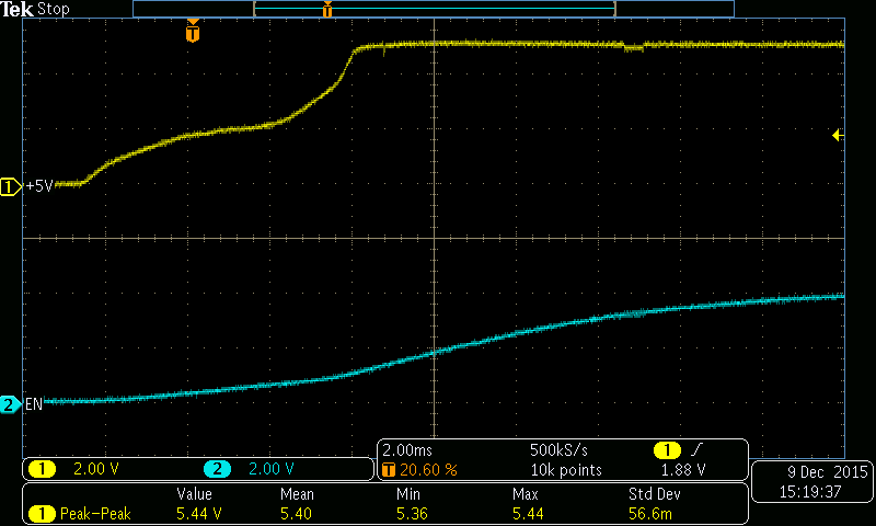
    You have me concerned about how we're handling the EN line. From what I heard you say, the EN line needs to experience a low-to-high transition while the device is powered up in order to function properly. Is that correct? Again, we have EN2 tied low. That would explain the capacitor, C28, that is connected to the EN line. It must be there in order to provide this rising edge. I captured the voltage on the EN line as well as the Vcc (=5V) to the board. I've attached the resulting scope plot. I  think the labels explain which signal is which. I don't see timing information for the EN signal in the data sheet in terms of the rise time or the amount of time Vcc needs to be stable before EN comes up, so maybe I can get your opinion on this measurement result please. 

     th

  • Josh,

    Have you had a chance to review this scope plot? I am very interested in the timing requirements for the EN signal on power up. Thank you.

  • Josh,

    I've been out for the Holidays. Have you had a chance to look at these scope plots? Can I get your opinion of them?

    David

  • David -
    thanks for pinging again on this, i was also out for holidays for some time

    regarding your plot - looks like EN is not controlled (looks like it is floating up) and very slow. i would ask you to please look at this and check that you follow section 3

    www.ti.com/.../sloa168.pdf

    in the old TRF7960 data sheet, we do talk about this topic, see figure 5-1, 5-2, and 5-3. I am not sure why we decided to omit this from the -60A DS, but for this topic, the devices will be same.

  • Josh,

    You are correct, we do not control the EN line. Please refer to the schematic I sent you. You'll find that the EN line is NOT under the control of a Microcontroller. Instead, this line is brought up slowly by placing a cap on it. Is there anyway to modify this design so that another control signal from the input connector is not required? I referred section 3 of the document you referred me to and I see what is required. However, can you provide timing information in terms of how long the power supply has to be up and stable for this to work?

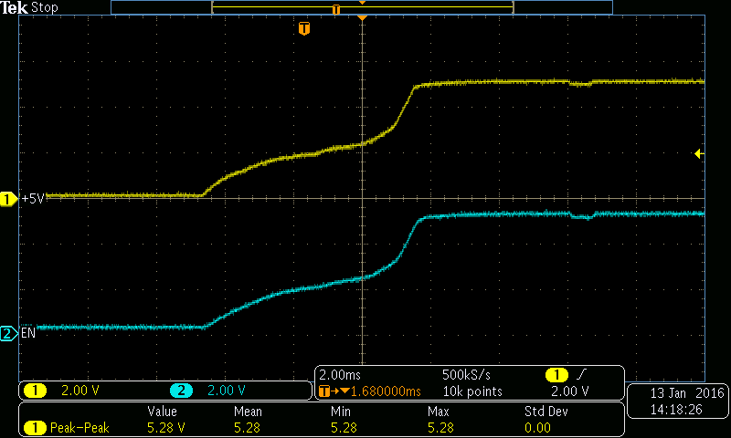
  • if you change R2 to 100 ohms and R9 to 10k, you will reduce your rise time from ~44mSec to about 1mSec, plus get above 4V (what you are limiting yourself to now. (would go up to 4.9VDC or so i think, no big deal, i think the faster rise is better here for you)
  • Josh, Thanks. I'll give that a try. The only alternative that doesn't involve another line back to the micro was to add a schmitt trigger between the R-C network and the EN pin. What do you think? That would involve a PCB spin, but at least the connections to the board can remain the same.
  • Josh, I forgot to thank you for being so prompt with your reply.
  •  Josh, Okay, this is what I get. The Enable line tracks the power supply as it comes up. Is this really what we want? The flow chart in SLOA168 Section 3 indicates the power should come up first and then the EN signal. That was the idea behind the slow rise time.

  • Josh, How are you doing. I haven't heard from you and I'd really like to put this issue to bed if possible. This EN line might be the source of my problem and I'd like to know how this line should be handled.
    Also, we have found that the range of our design is only about a quarter of what it should be, in case that's a clue. The expected range to the tag is expected to be 3.0". This is based on the diagonal measurement of the antenna of 1.5" which should equate to a 3.0" range. However. we seem to have a range that is only about 0.75". Does the range depend much on the tag?
  • Josh, Please review the concerns I raised in my previous message.

  • David -

    sorry for the delay

    The EN line is best controlled  by MCU. This is the recommendation. Otherwise,  the RC is about the best mitigation you have in your case.

    Regarding the reading distance - it depends on several factors which include power out of the device (your setting), tuning and Q and size of your reader antenna, tag size and protocol. Other factors are ambient noise and presence of metal or other tags.

    now then - with a reader antenna which is 1.5" in diameter and using an ID-1  (full size) ISO15693 transponder - i agree you should get perhaps a bit more range - would have to see what you have done here to comment further on your design

    you can see attached where we did read range measurements on two platforms, the second slide's antenna is 2cm x 2cm (this is smaller than your antenna) and we got 8cm, which is slightly over 3"

    if you have some design measurement data on the tuning of your antenna and the tag protocol and size of it to share - please let us know.

    TRF7960_Read_Range_Slides.pdf

  • Josh,

    Thank you for the good information. You mentioned the impact the environment can have on the performance of the RFID Board. I've attached a few photos of our RFID board and the area it is mounted in. Can you please comment on this design?

    This shows the RFID board we designed. Notice that the antenna PCA is separate from the PCA containing the TRF7960 and the antenna drive signals are brought over to the antenna board by a twisted pair wire harness.

    This shows the area the RFID board antenna is placed into. Notice the presence of metal all around the antenna.

    This is the same view as above with the antenna removed to provide a better view of the environment around the antenna. Is there a limit to the amount of metal that TI recommends being around the antenna for acceptable performance?

  • Josh,

    I still welcome your opinion on this design. As you can see, there is metal both around and underneath the RFID antenna we're using and I would like your opinion on what impact this might have on the performance of the TRF7960. In addition, we use a twisted wire pair to connect the antenna PCA to the PCA housing the TRF7960. I would be interested in you opinion of this aspect of the design also. Thank you.

    David

  • Josh,

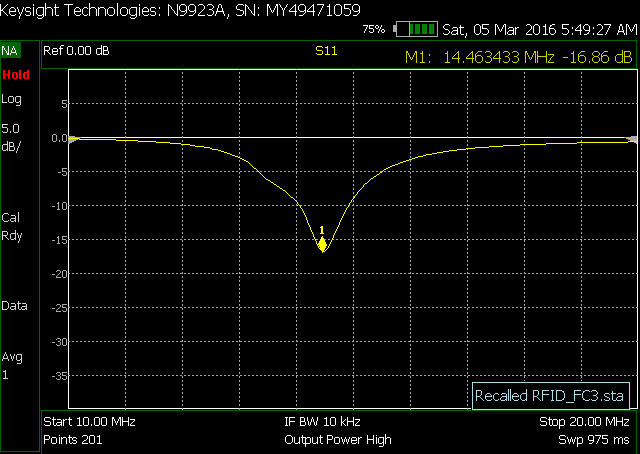
    Can I get your opinion on our design and some of the problems we're having. I rented a Network Analyzer to analyze the antenna matching circuit performance and here are the results with the antenna placed in the instrument with the metal mounting components. Can you have a look at this and render your opinion? Thanks.

  • sure - this is the plot of the log mag format showing center frequency as 14.463MHz.

    you need to be at 13.56MHz, so more capacitance is needed to shift you that direction

    if you look at the Smith Chart you will get better idea of whether you need it on parallel or series or a little of both, i suspect the latter to get it perfect.

    then in either this log mag format or SWR format, you can put up two additional markers on either side of fc (at +9dB of the fc on this screen) and at 2:1 SWR on that screen - this will give you a BW to calculate the Q from.

    just set the Q at around 8 for ISO14443A/B operations and around 16 for ISO15693 operations.
  • Josh,

    Thank you for the information. I have a few more questions, if you don't mind.

    We are running with ISO-15693. Please refer to SLOA135A. This document indicates a BW = 2 MHz should be used, for a Q = 13.56/2 = 6.78. Where does a Q = 16 come from? What is the impact on performance of using Q = 6.78?

    Please refer to SLOA140. This one has me very puzzled. On page 6 for Direct Commands, a variation of the SPI protocol is indicated that includes 9 clock cycles. Can you expand on this protocol and how it should be implemented? 

    David

  • David - 

    in SLOA135A, if you read just a bit further, it explains:

    A minimum bandwidth (BW) of 2 MHz is chosen in order to accommodate the upper and lower RFID sidebands for various data rates given in ISO15693 & ISO14443 A/B. 

    So to make it easy: 

    With ISO14443A and B, a lower Q is needed on the coil to accommodate the +/-848kHz subcarrier these tags use to communicate back their responses.

    The real (perfect) value is a BW of 1.696MHz (the app note rounds it up)

    With ISO15693, the subcarrier frequency of the response is +/-424kHz, so the BW is 848kHz with a resulting Q of 15.99, lets call it 16. 

    this EVM is set for lower Q as it does not impact ISO15693 range (much) if its ISO15693 only, then you can just move to higher Q and see some range improvement because your field strength will go up.

    on the SPI question - this is asking about resetting the FIFO with dummy clock options shown, because only one byte is being pushed through. the ones in question are marked 1 and 2  - these show 8 clock cycles like what would be generated for the 0x8F for the FIFO reset,one of several commonly used Direct Commands - then in blue a representation of extra clock behavior to satisfy the errata - 

    if you look on page 28 (figure 6-9) of the -60A data sheet - here is a logic analyzer capture of whole thing so its to me a complete picture to go with the description 


  • Josh,

    Thank you for the updated data sheet. 

    I still don't have a good handle on this problem. We have PCBs that work well and others that do not seem to be able to read the RFID tag reliably and I do not know why. What would you recommend I measure to find out how these two sets of PCBs differ? 

    I did examine the field strength between the passing and failing RFID PCBs and they were essentially the same. Would going from a Q = 7 like I have now to a Q = 16 be expected to improve this problem? 

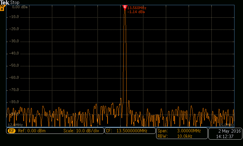
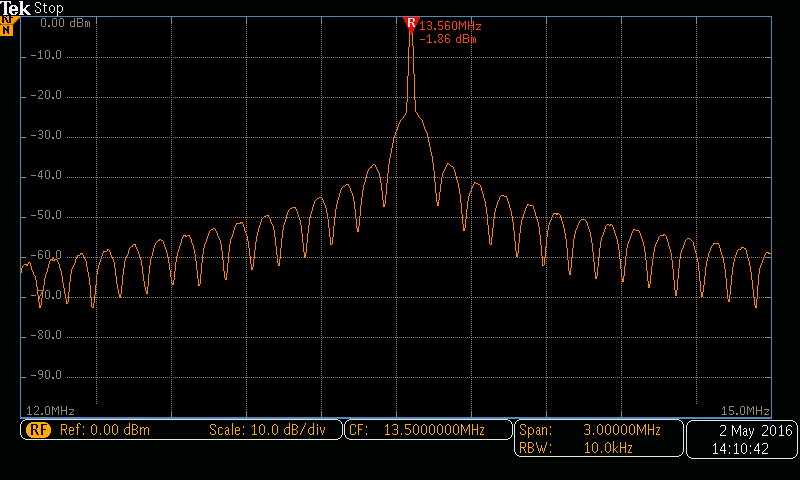
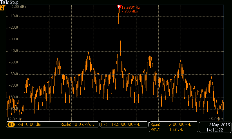
    I also captured the spectrum of the communication between the RFID PCB and the tag. I found three flavors:

    Some of these spectra seem too broadband for a Q = 16 to be used. Do you think going to a Q = 16 is worth a try?

    On the SPI bus, I see in SLOA140 Table 2 that only certain Direct Commands require the 9 clk transactions. The Transmit and Delayed Transmit commands require only 8 clks. I also understand that only commands require 9clks and not addresses, so bit B7 = 1 in this case. Is all this correct? All other communication requires only 8 clks, right? Referring to Table 6-11 in the data sheet you sent me dated Jan 2015, am I correct to assume that the Command Codes presented here are only for bits 0 through 4 and that Table 6-12 has to be used to represent the complete command hex value? Also, section 6.12.5 refers to the Direct Mode. How does this differ from Direct Commands?

    What is the best way to get a copy of the ISO 15693 standard? I think it would be useful to have a copy of this. 

    Maybe it would be easier to have a telephone conversation. My number is 510-723-9156.

  • i going back and looking at your pictures, i see you are using twisted pair for antenna cable - this is a bad idea unless you can control it precisely. you should move to coax cable or at very least controlled impedance ribbon.
    bottom line here is that i think you have some variability built in here that could be cleaned up which will help you make sure your firmware is correct after RF is squared away.

    ISO15693 is here ==> www.iso.org/.../catalogue_detail.htm (-2), www.iso.org/.../catalogue_detail.htm (-3)

    other option would be to send in a unit to the NFC/RFID apps team in Dallas for them to have a look for you.
  • Josh,

    I like to idea of sending our PCA to TI for you to have a look. I can even send a board that works reliabliy and one that does not. Please note that the instrument environment plays a role in this. That is, boards that fail in our instrument seem to operate just fine in a test fixture we have set up.

  • as much detail as you can provide - send me email at josh.wyatt@ti.com so i can then hook you up with apps team. (i left the group a couple months ago, but still at TI and as you can see i still do care :) )