This thread has been locked.

If you have a related question, please click the "Ask a related question" button in the top right corner. The newly created question will be automatically linked to this question.

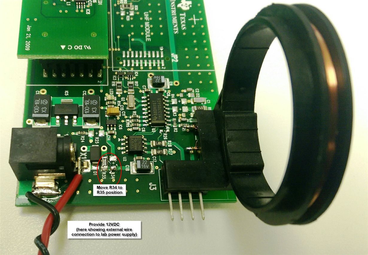
Can RI-STU-MRD2 attach external driver for more power?

Other Parts Discussed in Thread: RI-STU-MRD2, TMS3705, UCC27424

Hello,I'm FAE of distributor in Japan.

Customer ask me 2 questions.

1) Can RI-STU-MRD2 attach external driver for more power?

we have already got RI-RFM-007B information,but customer feel that RI-RFM-007B is expensive.

And E2E answer LF antenna.pdf information,but customer want more communication distance with more smaller antenna.

They want to add more current output from RI-STU-MRD2,is it possible?

TI have external gate driver solution with TMS3705,Does RI-STU-MRD2 have similer solution?

Or does TI have smaller antenna solution same which keep a communication distance?

2) Which page is UID(R/O)?
There is R/O page P3 in datasheet(scbs842b.pdf).
But I couldn't find page number of R/O.
I checked page 1 is programable and page 17 is all0.
I wonder R/O page is wrong description in datasheet.

Regards,

Shinya

  • Shinya-san - 

    please forgive the delay in replying. 

    Regarding question #1: the MRD2 could have an amplifier attached to it in the same manner which is shown here on page 13. 

    the original MRD1 could be "amplified as shown directly if one got on the other side of the NP Channel FET IC.

    The latest module (the MRD2) circuit is quite different - i would say that we would not recommend hacking into this circuit. 

    that said, the TMS3705 amplifier example is readily available here (on page 42): 

    note the rail voltage change required to amplifiy using that UCC27424 IC. If you want more, then you can design further along this line, with more heavy duty FET pairs and higher voltages (i think i would stop around 20-24VDC, as at the end of the day you are limited to about 20W in this band and when running near this power limit you will be pulling 2-3A most likely - maybe more - also note that as you raise the voltage rail, you need to have appropriate sized/rated components and coil materials for the kinds of voltage/current/power levels that you are working in. 

    Regarding #2: in this case, the explanation of the phrasing here is that in this transponder, you have a read only unique serial #, which can be retireved simply with a charge only read, as described in the reference manual for this transponder, located here first on page 10 and illustrated on page 16


  • Josh-san

    Thanks a lot for your response every time!

    I want to confirm this answer as follow.
    Does it means you recommend to use TMS3705? or RI-STU-MRD2 with UCC27424 is available?
    <- i would say that we would not recommend hacking into this circuit.
    that said, the TMS3705 amplifier example is readily available here (on page 42):>

    If RI-STU-MRD2 with UCC27424 is available,please inform us an additional question as follow.
    If customer attach UCC27424 with RI-STU-MRD2,How do they culculate external componet?

    Regards,
    Shinya Muramatsu
  • Shinya - 

    we do not recommend trying to amplify the MRD2 on your own. 

    instead, please take advantage of the hardware you can modify slightly and then use to evaluate the TMS3705 and the UCC device (this is the RI-ACC-ADR2 board, found here: http://www.ti.com/tool/ri-acc-adr2-10 )

  • Josh-san

    Thanks a lot for your response.

    > we do not recommend trying to amplify the MRD2 on your own. 

    OK,I understood.

    Our customer want more LF communication distance,and they want to change LF Reader.

    Before they change design,they want to evaluate base function easily.

    I have PALFI software and Automotive Demo software,but I heared these can't read TRPGP40 before.

    Do you have idea to evaluate easily?

    Regards,

    Shinya Muramatsu

  • Josh-san

    Please follow this additional request.

    They want to change LF Reader from MRD2 to their own board integrated TMS3705 because of not enough distance.
    They want to evaluate base function easily before they design it.
    I have PALFI software and Automotive Demo software,but I heared these can't read TRPGP40 before.
    Do you have any idea to evaluate communication TMS3705 and TRPGP40 easily?

    Regards,
    Shinya Muramatsu
  • in the PaLFI firmware, you can change the LF.c file to support RO/RW tags by changing the LFinit function (comment out PaLFI timings and insert RO/RW timings:

    void LF_Init(void)

    {
    //PWMtimes.usToffH = 480; //for PaLFI
    //PWMtimes.usTonH = 520;
    //PWMtimes.usToffL = 170;
    //PWMtimes.usTonL = 330;
    PWMtimes.usToffH = 1000; //for RO_RW_tags, JDW 09/17/2010
    PWMtimes.usTonH = 1000;
    PWMtimes.usToffL = 300;
    PWMtimes.usTonL = 1700;

    BLCtimes.usToff = 170;
    BLCtimes.usTonL = 230;
    BLCtimes.usTonH = 350;
    BLCtimes.usTonSC = 600;

    ucMCW1 = 0x7C;
    ucMCW2 = 0x7C;
    }

    then you should be able to also use the attached alternate GUI as well. 

    LF RFID DEMO BASE STATION.zip

  • Josh-san

    Thanks a lot for your kindly support.
    I found Reader firmware,I'll change and try.

    Regards,
    Shinya Muramatsu
  • Shinya-san, I can recommend an interface board offered by www.protagd.com. It connects an MRD2 to an RMF-007.

    BR
    K Seiberts