This thread has been locked.

If you have a related question, please click the "Ask a related question" button in the top right corner. The newly created question will be automatically linked to this question.

TRF7960A: TRF7960A doesn´t detect tag

Part Number: TRF7960A
Other Parts Discussed in Thread: TRF7970A

Hello,

I´m working with the TRF7960A with the MCU STM32F101RB, and my program follows this steps.

1- Enable the TRF EN=0 -> EN=1

2- Delay 10ms

3- Send to TRF de command 0x03 with the format 0x83. (I do this because I want all register be in default mode)

4-Delay 5ms

5-Send to TRF the single slot inventory 0x8F 0x91 0x3D 0x00 0x30 0x26 0x01 0x00, as the datasheet explains

6-Write in register 0x00, 0x20

7-Write ISO control

7.1- Write in register 0x01, 0x02

7.2- Write in register 0x0D, 0x3E

7.3- Write in register 0x09, 0x31

7.4- Write in register 0x06, 0x80

7.5- Write in register 0x07, 0x14

7.6- Write in register 0x08, 0x1F

7.7-

7.7.1- Read  register 0x0A, 0xYY

7.7.2- 0xYY &= 0x0F

7.7.3-0xYY |= 0x40

7.7.4- Writte  register 0x0A, 0xYY

7.8-

7.8.1- Read  register 0x10, 0xYY

7.8.2-0xYY |= 0xEF

7.7.3- Writte  register 0x10, 0xYY

7.9- Write in register 0x14, 0x0C

8-    Send to TRF the single slot inventory 0x8F 0x91 0x3D 0x00 0x30 0x26 0x01 0x00, as the datasheet explains

9- Wait an IRQ,

10- Receive an IRQ

11- Ask with 0x6C and dummy clock

12-Recive a 0x80

13- Receive an IRQ

11- Ask with 0x5C

12-Recive a 0x23, here is the problem

I should receive a 0x60, and I don´t Know how manage this data and what is its meaning. Could yo help me?


  • Hello Joseba,

    When you receive an IRQ you need to read the IRQ Status, not the FIFO Status. So you need to "Ask with 0x6C and dummy clock" as you stated each time you receive an IRQ.
  • Hi,

    When I receive an IRQ, and I ask with 0x6C, always answer with 0x80. It may happen due to the dummy clock is not send correctly? and because of this, the TRF´s IRQ is not reset and constantly generates the same interrupt? What do you think?

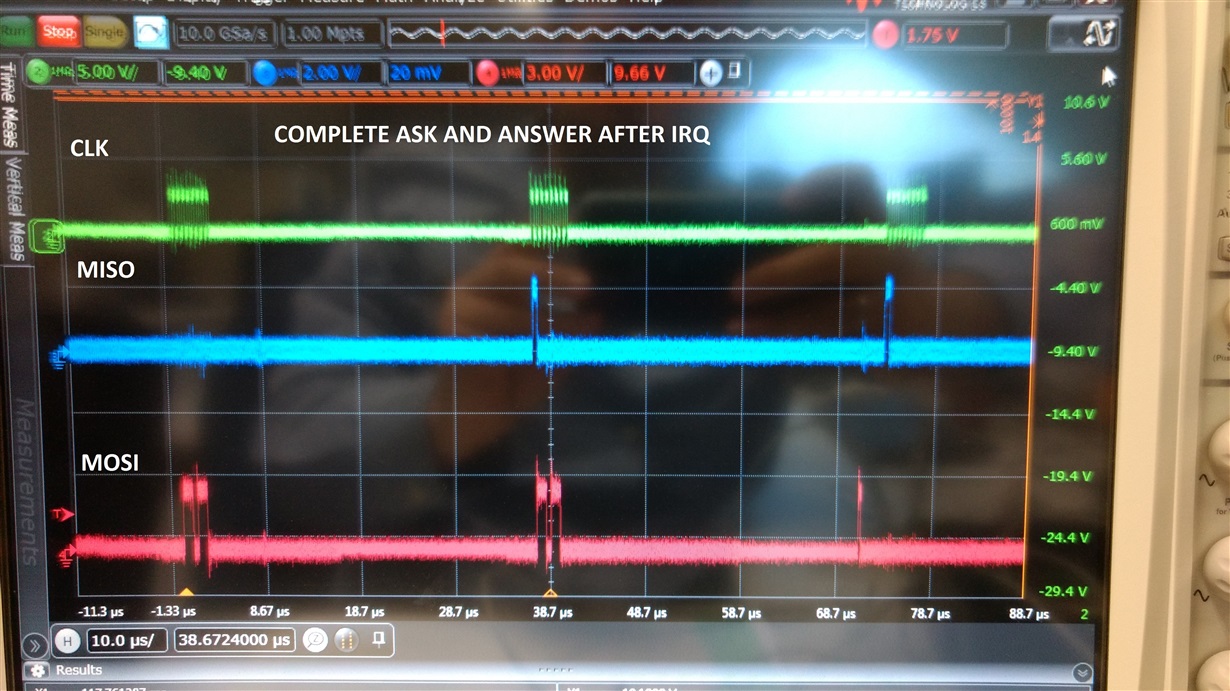
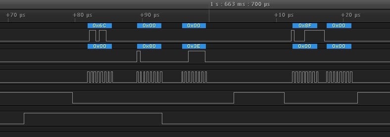
    I send you three scopes captures that explain what could be the problem. The figure 0 shows the complete communication after an IRQ. The figure 1, after receive an IRQ, I send to the TRF a 0x6C. Then, in the figure 2, you can see the answer of TRF, the answer is a 0x80. I think the problem occurs here. When I receive an answer from MISO (the expected answer 0x80). At the same time  (due to a bad configuration of SPI) I send again a 0x6C. This data could generate that in the dummy clock cycle, the TRF answer again with an 0x80, despite sending a 0x00 as dummy clock, and somehow this afects to the correct operation, and because of this I can´t read a tag. What do you think about it?

    Thanks

  • Hello Joseba,

    It looks like your MOSI line does not stay low when receiving the 0x80 command. This may be causing some issues. I've never really seen behavior where the MOSI line seems to be trying to re-transmit a 0x6C while receiving the 0x80. Please try and fix that behavior so your read and dummy clock looks something like this (also shows FIFO reset with dummy clocks)

  • Hi!

    I have solved the proble of MOSI data send while MISO is sending, and I send 0x8F and Dummy read, but still continued making an IRQ, why could it happen?

  • Hello,

    I have solved the last problem, but now when I send the inventroy request to de TRF, the TRF generate an IRQ. When I read the IRQ status register, the TRF answer with 0x81 (1000 0001). What does it mean?

    The inventory request that I send is:

    g_ui8TrfBuffer[ui8Offset++] = 0x8F;                    // Reset FIFO
        g_ui8TrfBuffer[ui8Offset++] = 0x91;                    // Send with CRC
        g_ui8TrfBuffer[ui8Offset++] = 0x3D;                    // Write Continuous

         ui16TransmitByteLength = ui8MaskByteCount + 3;    // Set packet size = Mask Value + Mask Length + ISO15693 Command Code + ISO15693 Request Flags 
                                                                      where   ui8MaskByteCount=0
        g_ui8TrfBuffer[ui8Offset++] = (uint8_t) (ui16TransmitByteLength >> 8);        // Length of packet in bytes - upper and middle nibbles of transmit byte length
        g_ui8TrfBuffer[ui8Offset++] = (uint8_t) (ui16TransmitByteLength << 4);        // Length of packet in bytes - lower and broken nibbles of transmit byte length
        g_ui8TrfBuffer[ui8Offset++] = 0x06,            // ISO15693 Request Flags
        g_ui8TrfBuffer[ui8Offset++] = 0x01;                    // Inventory Request Command Code

    Acordig to the document SLOA 138, page 12, table 2 IRQ STATUS REGISTER, it means that the IRQ was generated due to the end of TX, but no response was detectected (B7 1 and B0 1). If it is correct, that means I should read the nex slot, does it correct?

    But I don´t understand  if it  is posible the IRQ STATUS REGISTER answers with a byte tha contains more that one bit set. My question is,   if I read the TRF IRQ status register and  I read 0x81, the bit 7 and bit 0 are set to 1, and rest bits are set to 0.Could an IRQ answer  be accepted as correct  if more than one bits are set to 1?

    Thanks

  • Hello Joseba,

    Have you enabled the No Response Interrupt by getting Bit 0 in Register 0x0D?

    Yes the IRQ Status Register can have a byte with more than one bit set. It isn't always a good thing though. Sometimes (possibly in this case) it means you aren't servicing the IRQ quick enough, and other times it will report status such as a 0x44 or 0x50 which means that during RX, a framing or parity error occurred and the data is not good. Another case for multiple status reports is for ISO15693 tag collisions, often this returns 0x42 which means the RX has a collision occur.
  • I have solved the problem of the multiple set bits in IRQ register , but I am very hidden. This is the process I follow:
       1 Shipping the Inventory Request
    2 I receive an IRQ
    3 I read the IRQ status register
    4 Responds 0x80 and in the dummy clock 0x3F
    5 Reset FIFO with 0x8F
    6 Enable Slot Counter
    7 Check if the antenna is on. I read the registration 0x00 and it responds 0x01, therefore it is off
    8 Following the recommended code sloc297 of the TRF7970A. I expect the interrupt of RX in a loop of 16 slots
    8.1 I receive an IRQ
    8.2 I read the IRQ status register
    8.3 Responds with 0x01. Indicates IRQ for non-response
    8.4 Reset FIFO with 0x8F
    8.5 Stop Decoders (0x16)
           Run Decoders (0x17)
          Transmit Next Slot (0x14)
    9 I wait until another IRQ, but when I pass a TAG, the trf doesn´t detect any tag


    I think the problem is that the antenna goes off. I read the 0x00 register, and the TRF answers with a 0x01. That means the antenna is off. Because of this, I measure any signal with the oscilloscope on the antenna, and Icapture a 13MHZ signal. Anothe interesting thing is when I touch the antenna with the probe of the oscilloscope, the TRF generates an IRQ, but is not capable of detecting tags.

    As the code indicates, the first thing I do is activate the antenna, setting in the register 0x00 the value 0x21. But when I do the ISO control setup, something happens, that turns off the antenna and makes it impossible to turn it on.

    This is the configuration of the ISO control that I perform. You may see some registry misconfigured.

    Write [0] = TRF796x_ISO_CONTROL;
    Write [1] = 0x02;
    Write [1] & = 0xDF; // BIT5 to 0 to set RFID MODE
    Trf796xWriteSingle (write, 2);

    Iso_control & = 0x1F;

    Write [0] = TRF796x_IRQ_MASK;
    Write [1] = 0x3E;
    Trf796xWriteSingle (write, 2);

    Write [0] = TRF796x_MODULATOR_CONTROL;
    Write [1] = 0x31; // // OOK 100% 6.78 MHz
    Trf796xWriteSingle (write, 2);

    Write [0] = TRF796x_TX_PULSE_LENGTH_CONTROL;
    Write [1] = 0x80; // 9.44 us
    Trf796xWriteSingle (write, 2);

    Write [0] = TRF796x_RX_NO_RESPONSE_WAIT_TIME;
    Write [1] = 0x14; // 755 us
    Trf796xWriteSingle (write, 2);

    Write [0] = TRF796x_RX_WAIT_TIME;
    Write [1] = 0x1F; // 293 us
    Trf796xWriteSingle (write, 2);

    Write [0] = TRF796x_RX_SPECIAL_SETTINGS;
    Write [1] = TRF796x_RX_SPECIAL_SETTINGS;
    Trf796xReadSingle (& write [1]);
    Write [1] & = 0x0F;
    Write [1] | = 0x40; // bandpass 200 kHz to 900 kHz
    Trf796xWriteSingle (write, 2);

    Write [0] = TRF796x_SPECIAL_FUNCTION;
    Write [1] = TRF796x_SPECIAL_FUNCTION;
    Trf796xReadSingle (& write [1]);
    Write [1] | = 0xEF; // BIT 4 to 0-> Sets the TIME GRID
    Trf796xWriteSingle (write, 2);

    Write [0] = TRF796x_FIFO_IRQ_LEVELS;
    Write [1] = 0x0C;
    Trf796xWriteSingle (write, 2);
    ->In this point, the trf says me that the antenna is off

    Thanks
  • Hello Joseba,

    None of those should cause the Transmitter to turn off. When you observe this behavior, do you see the 13.56MHz output of the antenna disappear?

    Regarding the lack of tag responses, you should only get a response in the corresponding slot (based on last UID digit) for the tag you present, so you need to let it cycle though all 16 slots. The tag response should then be in one of those slots.
  • HI,

    The register 0x00 says that the antenna is off, but the 13.56MHz output doesn´t disappear, so it wants to say the TRF work properly, is ok?

    The problem of reading tags is that the trf does´t detect anything, although the antenna works. The TRF doesn´t generate an IRQ when I pass a tag. Only detects something when the tag touch directcly the antenna, and due to the contact, the TRF generates an IRQ. In the same way, when I measure with the scope and I touch the antena with the sounding line, the TRF generates an IRQ. 

    I prove reading the tags with my smarthphone and I´m capable of detect all tags, so I´m realy confused.

    Could you recommend me any test that help me to find a soluction?

    I have analyzed potential problems, and I think I may be misusing the inventory request.

    According to the anti-collision algorithm of sloa138, on page 3, the first point indicates that I have to check the bit 5 of the inventroy request flag. If the value is 1, the number of slots is 1, else 16. My question is, which  of the bytes I send in the inventory request  I have to check or change the bit 5 in order to select the 16 slots?

    As the pseudo-code in document sloa138 explains in page 4,  you have to send:

    buf[0] = 0x8f;                                    /* Reset FIFO command */
    buf[1] = 0x91;                                   /* Send with CRC */
    buf[2] = 0x3d;                                   /* Write continuous from register 1D */
    buf[3] = (char) (size >> 8);             /* Data for register 1D */  What is the meaning of this byte?
    buf[4] = (char) (size << 4);             /* Data for register 1E */  What is the meaning of this byte?
    buf[5] = 0x05;                                   /* ISO15693 flag with 16 slots bit set*/        What is the meaning of this byte?
    buf[6] = 0x01;                                   /* ISO15693 anti collision command code */ What is the meaning of this byte?
    buf[7] = length;                                 /* Mask length */
    If (length > 0)
    {
            for (i = 0; i < masksize; i++)
                      buf[i + 8] = *(mask + i); /* Mask value */
    }

    My questions are:

              1- How I order to the TRF that number of slots is 16, as I understand, by the inventory request

    2-The bytes I send ( from buf[0] to fuf[7]) is the inventory request? or one byte of this frame only is the Inventory Request?in this case which?

    3-The buf[5] is the byte which bit 5 should be set as 0, to select as 16 slots, is ok? 0x05 in binary is 0000 0101, the bit 5 is set to 0  its configure to 16 slots, what is the meaning of the first four bits?

    4- Acording to the document Sloa134,  Anti-collision algorithm explain:
                      1. The reader sends a mask value and number of slots along with the inventory request. The number of
                       slots can be 1 or 16.
                      2. The VICC compares the least significant bits of its UID to the slot number + mask value. If it matches,
                      it sends a response. If number of slots is 1, comparison is made on mask value only.
                      3. If only one VICC responds, then there is no collision and the VCD receives the UID.
                      4. If the reader detects a collision, it increments the slot pointer and makes note of the slot number in
                      which collision occurred.
                      5. The reader sends an EOF to switch to the next slot. The VICC increments its slot counter on reception
                     of EOF.
                      Steps 1-4 are repeated for all 16 slots.

    At the end of 16 slots, the reader examines the slot pointer contents. If it is not zero, it means that collision
    has occurred in one or more slots.
    To determine new mask value:
    1. Increment the mask length by 4.
    2. Calculate New mask = Slot number (in which collision occurred) + old mask.
    3. Decrement slot pointer by 1.

    5-the question is: for each slot I want to read, do I have to send an ineventory request?

    6- Arccording to the sloa 140 1.3 direct  command processing, all direct commands that are sent by SPI, they have to be send with a tx dummy. Because of this, each of the bytes that ire sent in the supposed frame of the inventory request, must be accompanied by a dummy clk, as the example shows:

    buf[0] = 0x8f;                                    /* Reset FIFO command */

    buf[1]=0x00;
    buf[1] = 0x91;                                   /* Send with CRC */buf[

    buf[1]=0x00;
    buf[2] = 0x3d;                                   /* Write continuous from register 1D */

    buf[1]=0x00;
    buf[3] = (char) (size >> 8);             /* Data for register 1D */  What is the meaning of this byte?

    buf[1]=0x00;
    buf[4] = (char) (size << 4);             /* Data for register 1E */  What is the meaning of this byte?

    buf[1]=0x00;
    buf[5] = 0x05;                                   /* ISO15693 flag with 16 slots bit set*/        What is the meaning of this byte?

    buf[1]=0x00;
    buf[6] = 0x01;                                   /* ISO15693 anti collision command code */ What is the meaning of this byte?

    buf[1]=0x00;
    buf[7] = length;                                 /* Mask length */

    buf[1]=0x00;

    Thanks

  • Hello Joseba,

    1- How I order to the TRF that number of slots is 16, as I understand, by the inventory request

    • 1 slot vs 16 slot inventory is determined by the command you tell the TRF7960A to issue. For the start of this application, I encourage using single slot inventory until you get a reply from that. Then you can do the 16 slot inventory using the anticollision process afterwards because that is more complex and advanced. Let's keep it simple until you get a tag reply.

    2-The bytes I send ( from buf[0] to fuf[7]) is the inventory request? or one byte of this frame only is the Inventory Request?in this case which?

    • The bytes are a combination of commands to the TRF7960A and the inventory request itself.

    3-The buf[5] is the byte which bit 5 should be set as 0, to select as 16 slots, is ok? 0x05 in binary is 0000 0101, the bit 5 is set to 0  its configure to 16 slots, what is the meaning of the first four bits?

    • As stated above, let's avoid 16 slots for now
    • Sending 0x05 is wrong even for 16 slot. You need to send a 0x06 for 16 slot. But for now, send 0x26 for single slot and see if you get a tag reply that way.
    • Also keep in mind that for the ISO15693 specifications, the lowest bit is Bit 0 and not Bit 1, hence why setting Bit 5 = 1 results in 0x26 and not 0x16.

    We'll address questions 4 and 5 once you get a tag reply from single slot.


    6- Arccording to the sloa 140 1.3 direct  command processing, all direct commands that are sent by SPI, they have to be send with a tx dummy. Because of this, each of the bytes that ire sent in the supposed frame of the inventory request, must be accompanied by a dummy clk, as the example shows:

    • No this is wrong.

    The direct command processing needing dummy clocks is exclusively for when direct commands are sent individually.

    In this case, the 0x8F should be followed immediately by the remaining data bytes, in a single transmission cycle, where SS never goes high until all 7 bytes are sent.

    What you posted will never work.

    Please follow the flow shown in TI example code I've provided for this, it is set up correctly for transmission.

    Furthermore, make sure to correct the ISO15693 flags to be 0x26 for single slot inventory to start.

  • Hi Ralph,


    According to your answer I have chosen to work with a one slot. Now I am able to detect cards, but not continuously, and whenever I dectecto a card, reading the register 0x0C, the TRF  responds with a 0x02. This means that a collision error occurs, in spite of being only one card next to the reader,  and I make sure the rest is not close to its field of action. According to the recommended code, when a 0x02 is read from the IRQ register, I should stop decoders, reset fifo and reset IRQ status. Should the latter only be executed after an interruption has occurred?

    Thanks 

  • Hello Joseba,

    It odd that you are getting a collision error but at least it looks you've gotten to the point of being able to send out a command and receive a tag reply. If there is only one tag present, there shouldn't be a collision though. Are you using TI hardware or custom hardware?

    That sequence of commands should only occur after an interrupt is detected.