This thread has been locked.

If you have a related question, please click the "Ask a related question" button in the top right corner. The newly created question will be automatically linked to this question.

TRF7960A: FIFO is always zero after sending the Inventory request for TRF7960A

Part Number: TRF7960A
Other Parts Discussed in Thread: TRF7960

Hello all,

I have a custom board which has STM32 controller as master and TRF7960 A is the slave for SPI communication. I could read and write to registers successfully. After sending Inventory request I do get an IRQ, when I check the status I get 0x80 and 0x3E which is same as shown in datasheet of trf7960 page 36. But after if I read the fifo register I get zero even though I have placed the rfid tag in the antenna vicinity. I have used the sample tags given by TI for TRF7960A EVM. 

After sending the below Inventory request I get the IRQ, when I read the IRQ status register I get 0x80,0x3E and after that I will reset the fifo (0x8F) and again I will get the IRQ but this time when I read the IRQ status I get 0x00 and 0x3E. How can that be zero? May I know where I am doing wrong. Any suggestion would help me a lot.

uint8_t req[10];
void Send_InventoryReq(void)
{
	TRF796xCheckRXWaitTime();
	
	req[0] = 0x8F;
	req[1] = 0x91;
	req[2] = 0x3D;
	req[3] = 0x00;
	req[4] = 0x30;
	req[5] = 0x26;
	req[6] = 0x01;
	req[7] = 0x00;
	
	//Reset the IRQ status register
	Trf796xResetIrqStatus();
	
	HAL_Delay(20);

spi_write(req, 8); }

  • Hello Sushil,

    Do you have the No Response Interrupt enabled in the Interrupt Mask Register (0x0D)?
  • Hi Ralph,
    Thanks for your reply. I checked the Mask register and its value is 0x3E which is the default value of register as described in the TRF7060A datasheet.
  • Hello Sushil,

    How much time elapses between getting the IRQ for 0x80 and checking the IRQ Status when you got the 0x00? Does the IRQ pin trigger prior to both IRQ Status reads?
  • Hi Ralph,
    a) The time elapsed is nearly 4ms between the first IRQ read and next IRQ.
    b) It triggers after the IRQ status read.

    I will explain in detail.
    1) I will send the Inventory request as shown in above post.
    2) I will get the IRQ, I will read the status where the values I get will be 0x80 and 0x3E. So I will clear off the fifo register 0x8F. The value of Mask register is 0x3E.
    3) I will get the IRQ again, I will read the status where the values I get will be 0x00 and 0x3E. I was supposed to get 0x60. Then if I read FIFO register its 0x00.

    Please let me know if I am missing any register write or following a wrong method to read the tag UID. Because getting the UID out of the TRF7060A is the main aim of my project.
  • Hello Sushil,

    As you are not using a TI MCU it may be difficult to help pinpoint whats going on.

    If you can get a Logic State Analyzer to capture the communication on SPI + IRQ that would help.

    From a software standpoint, the first thing to do is make sure the device is initialized and configured properly. This is the most likely issue.

    I would recommend to look at http://www.ti.com/lit/zip/sloc297 to see how to properly initialize and configure the TRF7960A. If you load it into CCS you can change the #define for TRF79xxA_VERSION to 60 to see the settings specific to the TRF7960A.

  • Hi Ralph,
    I dont have logic analyzer. I have a oscilloscope. I will capture the screen for spi and irq and send it across.

    I have cross checked with the source code you asked to check. All the initialization sequence are same, but I have found a weird behavior. When I enable the slot counter and send the inventory request I get the first IRQ and when I read the IRQ status I get 0x80 and 0x00. If I do not enable the slot counter, simply send the Inventory request then my first IRQ status would be 0x80 and 0x3E(As intended to get as per datasheet).
  • Hello Sushil,

    That is a bit odd indeed. I did some tests today with the TRF7960A and assuming all you changed was re-writing Register 0x0D to equal 0x3F then you should see the IRQ status be 0x80 0x3F. I presume that is what you meant by enabling the slot counter as that is what our reference firmware describes - please correct me if wrong.

    Can you check that if you read out Register 0x0D that is has been properly written?
  • Hi Ralph,
    Thanks for your reply. You are right. I had written a wrong value in the register. And enable slot counter meant the same meaning as in the reference firmware code. Now I get the 1st IRQ with values 0x80 and 0x3E but 2nd IRQ is still 0x00 and 0x3E.
  • what are your inventory request flags set to (byte before the command byte in the ISO15693 protocol)?

    for example, if you sending single slot, should be the bytes: 0x26 0x01 0x00, if doing sixteen slots, should be: 0x06 0x01 0x00, then followed with 15 EOF/Slot Markers. 

    see page 34 here ==> 

  • Hi Ralph,
    I have used the same frame structure as shown in the given doc page 34. 2nd IRQ is 0x00 and 0x3E.
  • Hi Ralph,
    I have observed that the signals at antenna are not getting any modulations at all. It is constant through out. Please find the attachment below. Since its OOK I was expecting ON-OFF in the signal which we can clearly notice in trf7960a EVM. Just for testing purpose I have connected the SPI lines, EN line from my custom board and disconnected MSP430 in the EVM and observed the aforementioned antenna signal. Can

    you tell me where I might be doing wrong?

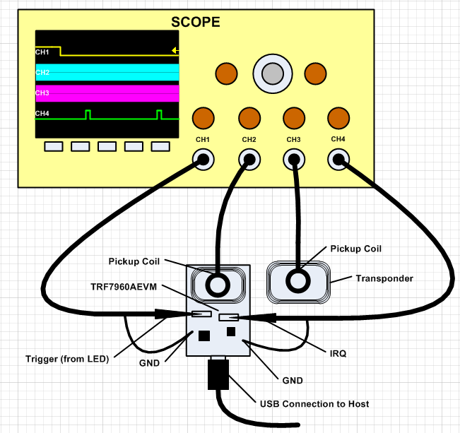
  • should be able to use the attached and walk through your signal path

    7215.TRF79xxA_Test points_05_2013.pdf

  • also - you can use the attached for reference if you want to see what over the air looks like and see the downlink and uplink

    using this as a setup example: 

    ISO15693_Screen_Captures.zip

  • Hi Josh,

    Thanks for your reply. I will test with the provided test points and get back to you.

  • Hi Josh,

    I have tested my custom board as per the above doc and attached the compressed file where it contains the signal capture in my oscilloscope between the TRF7060A_EVM and my custom board which is having TRF7960A. The image name in the .rar gives the description of the respective image. I have also attached my schematic. Let know if there are any suggestions from your end on the issue.

    TRF7960_SignalTest.rar