This thread has been locked.

If you have a related question, please click the "Ask a related question" button in the top right corner. The newly created question will be automatically linked to this question.

TRF7960A: What is the normal initiation process to make TRF7960A working well?

Part Number: TRF7960A
Other Parts Discussed in Thread: TRF7970A

hi,

my customer design a TRF7960A + ST MCU to be an NFC Reader,

we found the IRQ pin always has no response while put a NFC card(ISO15693) near to TRF7960A's antenna.

we check the VIN +5V is normal, and the pwoer sequence of VIN, EN, SS is matached in DS, and 13.56MHz crystal is normal,

so my question is, how to initiate the TRF7960A well?

(we sent the SPI read command, but SOMI always has no data output)

  • Hello erik,

    There is a section from the TRF7970A datasheet which is relevant for this which I'll post for your reading:

    That all applies for the TRF7960A as well.

    Are they applying the correct SPI polarity for read command and then changing polarity when receiving data? See http://www.ti.com/lit/an/sloa140a/sloa140a.pdf for full details on this.

    To properly initialize the TRF7970A, perform these steps: 1. Raise the EN, EN2, and SS lines at the correct intervals after power up (for timing diagrams, see Figure 6-3 and Figure 6-4). 2. Issue a Software Initialization direct command (0x03), followed by an Idle direct command (0x00) to soft reset the TRF7970A. NOTE Table 6-21 lists the initial register settings for the TRF7970A after the Software Initialization command. 3. Delay 1 ms to allow the TRF7970A to fully process the soft reset. 4. Issue a Reset FIFO direct command (0x0F). 5. Write the Modulator and SYS_CLK Control register (0x09) with the appropriate application-specific setting for the crystal and system clock settings. 6. (Optional) Write the Regulator and I/O Control register (0x0B) with the appropriate application-specific setting.

  • Dear Ralph,
    Thanks for your reply, some question still need to confirm with you:
    1. if the EN PIN always makes it HI(never get into sleep or power down mode), does it need to control the EN2?(else of EN2, the timing of VIN/EN/SS is correct on customer's TRF7960A)
    2. So TRF7960A INIATE process is same withTRF7970A(Step1~6)?
    3. For the IRQ PIN, as description in DS, it works when END of TX or START of RX or ... depends on the status in register 0x0c, does the IRQ PIN only work well after correct initiation process? so far, customer put a TAG near the TRF7960A's antenna, the IRQ's level doesn't change, does that mean initiation process fail?
    4. How to easily confirm the initiation process be well done?
    Thank you.
  • Hello Erik,

    1) No you wouldn't need to control EN2 then. Most designs just tie EN2 to ground anyways. (If you do this and want MCU control as well, please use a 10k pulldown resistor)

    2) Yes.

    3) The IRQ needs more than just a correct initialization process to trigger. You need to also issue commands to the tags. The TRF79xx devices are NFC transceivers, not NFC controllers. They need very detailed handling from the MCU. All commands must be prompted from the MCU and all responses must be processed by the MCU. The IRQ is there to assist with this process to inform the MCU when it needs to act after issuing commands.

    4. Read the last (or all) register that was written to and ensure the contents are correct is probably the easiest?

    It sounds like your customer may be trying to develop an application from scratch with little device understanding. They must reference TI firmware.

    For a full NFC implementation they should refer to: http://www.ti.com/lit/pdf/sloa227

    For basic RFID functionality, they can just refer to the RFID reader example detailed here: https://e2e.ti.com/support/wireless_connectivity/nfc_rfid/f/667/t/493678

    Since they not using a TI MCU, we will only assist with device related questions. Firmware implementation will be up to them to handle.

  • Dear Ralph,

    Thank you.

    Now customer can read the data from MISO PIN, but it not success every time.

    what things need to be careful to ensure MCU can read out data from TRF7960A?

  • Hello Erik,

    Section 6.12.6.2 of the datasheet titled Serial Interface Mode With Slave Select (SS) covers all aspects and includes screenshots of communication. The customer can reference this to make their SPI driver more robust.
  • Dear Ralph,

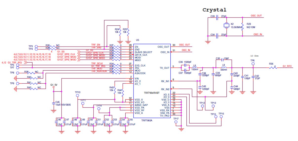
    our customer now is concern whether the un-stable status cause by HW design, they put some questions as below:

    1> does the external 13.56MHz crystal require special spec?

    2> what is the spec of C33 & C34(as schematic below) should be?

    3> is there anything wrong in schematic? 

  • Hello Erik,

    1) The crystal recommended characteristics are detailed in the device datasheet table in Section 6.8 under Table 6-5.

    2) The capacitors were chosen based on crystal datasheet. Caps for each application will depend on crystal datasheet/requirements. They should check the requirements for their crystal.
    - Additional note, the crystal stability can be checked by looking at Bit 6 of Register 0x0F after startup. If they are worried about the crystal, this would be a good step to take.

    3) MOD and ASK/OOK should have 1k pulldowns. Everything else looks fine!
  • minor catch - make sure VDD_X and VDD_I/O are connected on the layout. looks like you intend that to be the case, but you have no junction there - it might still be OK, based on your CAD tool - please just double check that before you make boards that its truly connected - or if you have already made them - check same with ohmmeter.

  • Hi Josh,

    Great catch! If that junction isn't made right then VDD_X would be floating too which would be a big problem and could cause reliability issues. Thanks!