This thread has been locked.

If you have a related question, please click the "Ask a related question" button in the top right corner. The newly created question will be automatically linked to this question.

TRF7970A: TRF79xxA_turnRfOff() doesn't switch off RF

Part Number: TRF7970A

I've designed own board with TRF7970A. But it doesn't switch off RF, even B5 (pwr_on) in StatusRegister is zero. When I ignore result of TRF79xxA_checkExternalRfField() it works well.
The same program on DLP-7970A works well -> TRF79xxA_turnRfOff() switches RF off.
Is it result of wrong pin connection (I/O_0 - I/O_7 pins) or something else?
Thanks,
Vladislav

  • Hello Deco,

    I am not sure what you mean by "When I ignore result of TRF79xxA_checkExternalRfField() it works well."

    If bit 5 of the Chip Status Control register is 0x00 then the RF field should be off. How are you measuring the RF field being present? O-scope? Pickup coil?
  • Hello Ralph,

    You can ignore checkExternalRfField() from previous.

    I've measured signal on pin TX_OUT (pin 5) and also with coil today. There is always signal on TX_OUT, regardless setup of bit B5 of status control register (adr 0x00). EN2 is always connected to Vio in my design. I'm not able to switch it off (TX_OUT). I've tested the same on DLP 7970A and it works well -> TX_OUT is switched on/off according bit B5 of status controll register. What I found, that DLP7970 has EN2=0 and it is powered from 3V.

    I've tried to connect EN2 to GND but it didn't work. What can I try more?

    Thanks

    Regards,

    Vladislav

  • Hello Deco,

    I'd need to see the schematic for the TRF7970A on your design to start with as far as debugging goes.

    Also what MCU/software are you using on your board?
  • Hello Ralph,

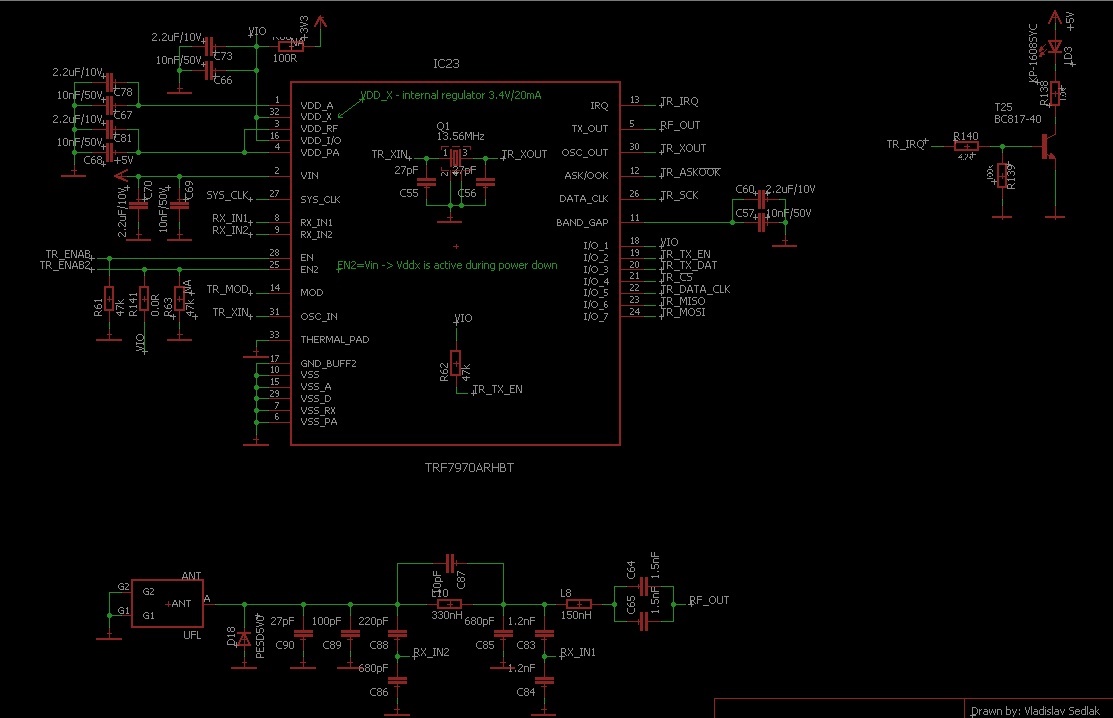
    Below is schematic. I've ported sloc297c.zip to STM32L4 (SPI mode + CS). It works well, I'm able to communicate with DESfire card. But I have to I ignore that TX_OUT is always ON ( TRF79xxA_checkExternalRfField() returns true ).

    Thanks,

    Vladislav

  • Hello Deco,

    Thanks for the schematic, have some questions and feedback on it.

    1) VDD_X and VDD_I/O seem to be tied to a 100Ohm resistor going to 3.3V - is this meant for VDD_X to be a 3.3V source? Also I think the NA near that component means it isn't populated, is that correct?

    2) MOD and ASK/OOK are going to the MCU, yes? If so they should be pulled down using internal MCU pulldowns. Externally 1kOhm pulldowns are recommended should you make future board changes.

    3) Not sure what the IRQ circuit with the transistor on the upper right is for, can you explain?

    From a software standpoint:

    1) Have you read out other registers with non-zero values to ensure they are correct? Such as 0x0F which should return Bit 6 = 1 after the TRF7970A is brought up (indicates 13.56MHz crystal is stable)

    2) How are you triggering the TRF79xxA_turnRfOff() function? Do you have a breakpoint set after it to make sure no other function may turn on the RF field?

    3) How are you using TRF79xxA_checkExternalRfField and in what situation? This is used to check if an external RF field is present, not the TRF7970A's own RF field. Rather if you have another NFC present emitting an RF field, the TRF7970A would be able to detect it with that firmware and then the TRF7970A can be configured to not send out it's own which would create an RF field collision.

  • Hello Ralph,
    Thanks for advices.
    1) R60 isn't populated, Vdd_io is connected to Vdd_x - internal regulator
    2) MOD and ASK/OOK are unconnected. I'll try to add 1kOhm pull down. -> would MOD pin cause this behaviour?
    3) it is just LED indicator of IRQ activity
    FW
    1) I've checked register 0x00, 0x01, 0x09, 0x0b and 0x0F. There were correct (expected) values.
    2) I'm sending register values to UART. But also breakpoints has been used. Other function shouldn't change reg. values. I've check also SPI activities on the osciloscope.
    3) We ignore TRF79xxA_checkExternalRfField() for now.
    Regards,
    Vladislav
  • Hello Deco,

    I don't think I've heard of the MOD pin cause that issue.

    Regarding other functions changing the register value, keep in mind all calls of TRF79xxA_setupInitiator() will turn the RF field on. So you need to make sure that function isn't being called after you set the RF field off. That is the only other function other than TRF79xxA_turnRfOn() which will turn on the RF field. Do you know if that function may be being called after TRF79xxA_turnRfOff()?

  • Hello Ralph

    I've done some tests today. I've found that if I connect Vin to 3.3V it works as I expected (also with change bit0 in config status register). It doesn't work properly only on 5V.

    But 3.3V reduces reading range. Do you have any suggestion what could be wrong in 5V setup?

    Best Regards,
    Vladislav
  • Hello Deco,

    Hmmm, it won't turn off on 5V but will on 3.3V?? That really isn't something I've ever seen or heard of before. Have you tried this on multiple boards and had all the same result? I wonder if maybe something is suspect with the soldering of the board or the chip itself. Multiple boards would indicate one way or another typically.

    The only other thing I can think at the moment to even give a clue is to get a full register readout from SPI of the TRF7970A registers when the RF field is erroneously transmitting.
  • Vladislav -
    R62...replace that with 0 Ohm and tie those to VDD_X. I/O_0 (not shown on your schematic) should be going to GND>

    Also, EN and EN2 should have 10k pulldowns and as Ralph said, ASK/OOK and MOD need 1k pulldowns (those are inputs!!!)

  • Hi Josh,

    Hmm... Think the 47k Resistor on I/O_2 is sucking up too much current? Though VDD_I/O is tied to VDD_X so that part should be okay at least which is why I didn't comment one way or another on that.

    Also from my interpretation, I/O_0 was curiously renamed to be GND_BUFF2 as that is Pin 17 so I think that part is okay at least...
  • The two lines (I/O_1 and I/O2) need to be at same potential. The 47k between them prevents that. they can be both tied to VDD_I/O (in this case also tied to VDD_X, which is ideal) with 10k pullups or both directly to VDD_I/O.

    Also, this would put the device in an unknown state, as the way it is wired up, I/O_1 would be at VDD, I/O_2 would be near GND. This combination would not be accommodated by the TRF79xxA devices according to the table 6-10 on page 31 of the data sheet for either SPI w/SS or without.


    if the true intent of the system is to do Special Direct Mode, I/O_1 would be held high and I/O_2 would be under MCU control, as described here: 

    Based on naming of the nets in the schematic, i suspect this might be the case. 

  • Hi Josh

    IO_0 (pin 17) is on GND, IO_1 on Vio and IO_2 on HIGH level by microcontroller (Vio). EN2 is on Vio, EN and SS are initialized according 6-3 p21. I've also connected MOD and ASK/OOK directly to GND.
    I've tried also disconnect Vdd_x (3.38V) from Vio and Vio connect to internal 3.3V (the same source as microcontroller) without success.
    What I found, that TX_OUT emits 13.56 MHz signal after ModulatorControl register (0x09) is initialised (after reset there is 0x91, after initialisation 0x01).
    I've decided to connect power supply (Vin) to 3.3V, although reading range will be shorter. Maybe I'll return to try solve it in future. The best would be if some development board of TRF7970A powered 5V exists to compare and measure.

    Regards,
    Vladislav
  • Hello Deco,

    The TRF7970ATB is powered at 5V with an on board LDO.

    The NFCLink Bundle: https://store.ti.com/NFCLink-Evalution-Kit-P4617C42.aspx is probably what you will want, it works with our SLOA227 firmware so you can measure the TB with the TRF7970A working at 5V. http://www.ti.com/lit/an/sloa227a/sloa227a.pdf

  • Hello Ralph,

    I've bought TRF7970ATB and an issue seem to be solved. The problem was in ENABLE2 signal. It has to be tied to GND not to Vio.

    Signals connections:
    TR_ENAB - microcontroller
    TR_MISO, TR_MOSI, TR_SCK, TR_CS, TR_IRQ - microcontroller
    TR_ENAB2 - GND
    Vin = 5V
    IO_0(pin 17) = GND
    IO_1(pin 18) = Vio
    TR_TX_EN(pin 19) = Vio

    TR_ASK/OOK and TR_MOD are free on my PCB, but on TRF7970ATB I had set to HIGH.

    Thanks for your time.

    Vladislav