This thread has been locked.

If you have a related question, please click the "Ask a related question" button in the top right corner. The newly created question will be automatically linked to this question.

RF430CL330H: Harvested Power from a typical NFC-enabled smartphone of RF430CL330HTB using the onboard antenna

Part Number: RF430CL330H
Other Parts Discussed in Thread: DLP-RF430BP, , TIDA-00721, MSP430G2553, TIDA-00217

To whom it may concern,

I am Binh, Now I am using RF430CL330HTB controlled by a MSP430 MCU to read data from some sensors, so I want to ask you about the problem that I am confusing, could you please let me know:

1)  Did TI make any measurement about the power received from a NFC-enabled smartphone using the on-board antenna of the RF430CL330HTB. Because I would like to know whether it is enough to drive the MCU and sensors whose total power consumption is approximately 3 mW.

2) If I want to use external antenna for this board, does TI provide any reference for consumers to determine the appropriate antenna geometry? Thank you so much.

Sincerely,

Binh Nguyen Thanh

  • Hello Binh,

    You'll be right up on the limit if you are at 3mW. An RF field in general can provide ~1mA of current, which are 3.3V would be 3.3mW of power. This is a general estimate though, and it can vary across smartphones, so not all phones will provide you that much current.

    We don't have any reference for antenna geometry, but we do have an antenna tuning guide that gives you some basic details to consider. Ultimately antenna topology is up to you and your application. Keep in mind if you are new to HF RFID/NFC that the RF field is magnetic and the antenna coils rely on inductive coupling to transfer power/data, so you want the antenna sizes to match up as best as possible (please note that smartphones have varying antenna sizes). The app note is: http://www.ti.com/lit/pdf/sloa197

  • Hello Ralph,

    Thanks for your explanation. I also have one more issue that I need your help to make it clear. Do the components of the RF430Cl330HTB board affect to the magnetic flux through the antenna? Because I read in some other documents that we should allocate a dedicated area for the antenna to have the best performance, thank you.

    Sincerely,

    Binh Nguyen Thanh

  • Hello Binh,

    They can if they are laid too closely to the antenna, which is why the dedicated area concept is presented, but there are many ways to create a dedicated area. For example, on a smaller board, you can have all components within the perimeter of the antenna: http://www.ti.com/tool/TIDA-00217 which works because no traces cross over with the antenna.

  • Hello Ralph,

    I see that there is a rectification circuit with Schottky diodes and storage capacitor in www.ti.com/.../TIDA-00721 and www.ti.com/.../TIDA-00217, but I didnt see it in the schematic of RF430CL330HTB target board, so how can we convert harvested AC signal to DC for the transponder and MCU? Moreover, I would also like to know whether the rectification circuit affect to the resonating circuit because I see that it is laid in parallel with the antenna and Cres, thank you.

    SIncerely,

    Binh Nguyen Thanh
  • Hello Binh,

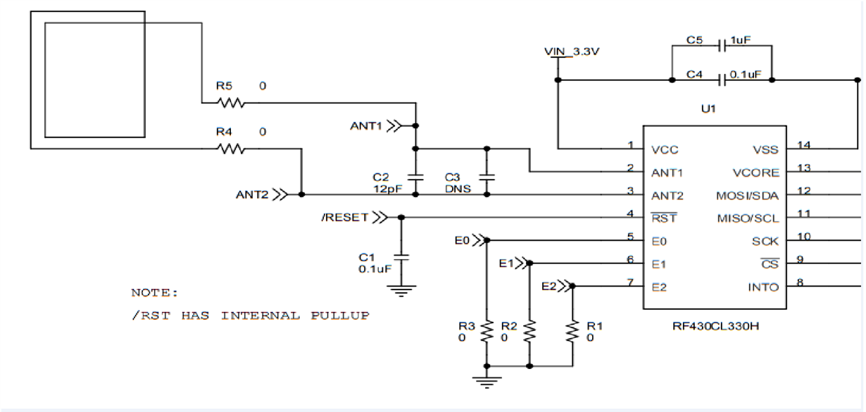
    Sorry for my misunderstanding of the exact application you are trying to achieve with the RF430CL330HTB board specifically. That board doesn't have support for the type of field powered application we are discussing built in on the PCB, though you could add the diodes and capacitor to it with some soldering. It wouldn't look pretty, but should be functional.

    Alternatively, you can get the DLP-RF430 BoosterPack which has those components included and works with the LaunchPad ecosystem to give you more MCU options.
  • Hello Ralph,

    I've already read the DLP-RF430BP BoosterPack datasheet and I see in the schematic that it doesn't include rectification circuit as shown in the image attached below, so I want to ask you are there any evaluation boards with RF430CL330H that provide both rectification circuit and on-board antenna, it'll be more convenient for my work.

    As you mentioned, I can add a rectification circuit by soldering Schottky diodes into the RF430CL330HTB board. But this board was designed for another purpose, so is the antenna optimum for my application? because in my work I need the antenna to harvest as much energy from the source as possible for driving the sensors, thank you.

    Sincerely,

    Binh Nguyen Thanh

  • Hello Binh,

    Where did you find that datasheet from?

    The latest datasheet is: www.dlpdesign.com/.../dlp-rf430bp-ds-v12.pdf

    That shows the diode and capacitor on it.

    As far as modifications to the target board goes, the antenna itself should be fine, but whether the circuit will work as efficiently as you'd like compared to the BoosterPack, I can't really say. It's not a modification I've tried personally, just an idea you could consider.
  • Hello Ralph,

    Thanks for your help. I've already seen the rectification circuit in this link. But I see in RF430CL330H Booster Pack and some other evaluation boards with RF430CL330H NFC transponder that they don't contain impedance matching circuit, so could you please let me know what the reason is? thank you.

    Sincerely,

    Binh Nguyen Thanh
  • Hello Binh,

    There isn't an impedance matching circuit needed for the device. Only a resonance frequency tuning capacitor. See details in Section 6 of the RF430CL330H Antenna tuning guide: http://www.ti.com/lit/pdf/sloa197

  • Hello Ralph,

    I connected the RF430CL330H Booster Pack and the MSP-EXP430G2 board together using the sample code to display the string "Hello, world!. With the power is supplied from the lauchpad , it worked very well. But when I removed the MCU from the lauchpad and tested it on a breadboard, it stopped working, then I supplied a 2.7V to VCC and GND pins by a DC generator, it worked again, so it demonstrated that the on-board antenna didn't harvest enough energy to operate in fully passive mode, so I am confusing that was the on-board antenna of the RF430CL330H Booster Pack designed only for data communication? Because I see it has the rectification circuit which is usually designed for energy harvesting. Thank you!

    Best Regards,

    Binh Nguyen Thanh

  • Hello Binh,

    The BoosterPack design is fine, our example firmware however is not optimized for Low Power Modes and doesn't allow for that demonstration. Updating the code to show off passive operation is an item on my table, but it is a low priority item currently with no timeline estimate.

    Also if you are going to use passive operation, you must remove all the jumpers between the G2553 and the ICDI circuit programming it or else the ICDI will be backpowered and source too much current to allow the G2553 to operate even with low power optimizations.

  • Hello Ralph,

    In my experiment, I already removed all the jumpers between MSP430G2553 and the ICDI programming circuit but it also didn't work. I don't really understand why you said that "Updating the code to show off passive operation is an item on my table" because I see in TIDA-00217 and TIDA-00721 they can run a temperature in a passive mode with the same line of MCU and NFC transponder, thank you.

    Best Regards,

    Binh Nguyen Thanh

  • Hello Binh,

    The MSP420G2xx and MSP430FR5xx families are very different lines of MCU's for TIDA-00217, especially in terms of power consumption which is crucial to manage for the application you are attempting.

    TIDA-00721, would be much more applicable to your application - I had forgotten about that design TBH because while I assisted with it, it's own by the Temperature Sensor team. That would be a good reference for you to leverage to modify the G2553 firmware to enable passive mode on the LaunchPad.

    That said, my comment about updating code is very much true because it was in reference to the G2 LaunchPad code which even if using TIDA-00721 as a base, would need to remove the ADC functionality, and then adjust the pinout from the TI Design layout to adapt to the BoosterPack+LaunchPad pinout. Less intensive than adding Low Power Modes to the base TI example, but still will require some efforts.