


Hello friends!
I have two CC2500 modules, one as TX mode and the other as RX mode.
I developed MCU with ATSAMD21G, but based on the "MSP-CC" example.
I configured both tx and rx as under below.
        rf_write_one(TI_CCxxx0_IOCFG0,   0x06);  // GDO0 output pin config.
	rf_write_one(TI_CCxxx0_PKTCTRL0, 0x05);  // Packet automation control.
	rf_write_one(TI_CCxxx0_CHANNR,   0x03); // Channel number.
	rf_write_one(TI_CCxxx0_FSCTRL1,  0x0A); // Freq synthesizer control.
	rf_write_one(TI_CCxxx0_FREQ2,    0x5C); // Freq control word, high byte
	rf_write_one(TI_CCxxx0_FREQ1,    0x4E); // Freq control word, mid byte.
	rf_write_one(TI_CCxxx0_FREQ0,    0xC4); // Freq control word, mid byte.
	rf_write_one(TI_CCxxx0_MDMCFG4,  0x86); // Modem configuration.
	rf_write_one(TI_CCxxx0_MDMCFG3,  0x83); // Modem configuration.
	rf_write_one(TI_CCxxx0_MDMCFG2,  0x03); // Modem configuration.
	rf_write_one(TI_CCxxx0_MDMCFG1,  0x23); // Modem configuration.
	rf_write_one(TI_CCxxx0_MDMCFG0,  0x3B); // Modem configuration.
	rf_write_one(TI_CCxxx0_DEVIATN,  0x44); // Modem dev (when FSK mod en)
	rf_write_one(TI_CCxxx0_MCSM0 ,   0x18); // MainRadio Cntrl State Machine
	rf_write_one(TI_CCxxx0_FOCCFG,   0x16); // Freq Offset Compens. Config
	rf_write_one(TI_CCxxx0_FSCAL1,   0x00); // Frequency synthesizer cal.
	rf_write_one(TI_CCxxx0_FSCAL0,   0x11); // Frequency synthesizer cal.
And strobe as TI_CCxxx0_SRX with RX module, and TI_CCxxx0_STX with TX module for RX mode only and TX mode only.
And transmit data like under belows.
		txBuffer[0] = 0x7F;							// Burst Address
		txBuffer[1] = 2;							// Packet length
		txBuffer[2] = 0x01;							// Packet address
		txBuffer[3] = 0x05;							// prearm_code
		RFSendPacket(txBuffer, 4);


void RFSendPacket(char *txBuffer, char size)
{
	rf_write_buf(TI_CCxxx0_TXFIFO, txBuffer, size); // Write TX data
	TI_CC_SPIStrobe(TI_CCxxx0_STX);           // Change state to TX, initiating // To make

	while (!(port_pin_get_input_level(TI_CC_GDO0_PIN)));
	// Wait GDO0 to go hi -> sync TX'ed
	while (port_pin_get_input_level(TI_CC_GDO0_PIN));
	// Wait GDO0 to clear -> end of pkt

}
And received data like under belows.
char RFReceivePacket(char *rxBuffer, char *length)
{
	char status[2];
	char pktLen;

	//TI_CC_SPIStrobe(TI_CCxxx0_SRX);

	while (!(port_pin_get_input_level(TI_CC_GDO0_PIN)));//GDO0_PIN
	while (port_pin_get_input_level(TI_CC_GDO0_PIN));//GDO0_PIN

	if ((TI_CC_SPIReadStatus(TI_CCxxx0_RXBYTES) & TI_CCxxx0_NUM_RXBYTES)) //
	{
		pktLen = TI_CC_SPIReadReg(TI_CCxxx0_RXFIFO); // Read length byte

		if (pktLen <= *length)                  // If pktLen size <= rxBuffer
		{
			TI_CC_SPIReadBurstReg(TI_CCxxx0_RXFIFO, rxBuffer, pktLen); // Pull data //
			*length = pktLen;                     // Return the actual size
			TI_CC_SPIReadBurstReg(TI_CCxxx0_RXFIFO, status, 2);
			return (char)(status[TI_CCxxx0_LQI_RX]&TI_CCxxx0_CRC_OK);
		}                                       // Return CRC_OK bit
		else
		{
			*length = pktLen;                     // Return the large size
			TI_CC_SPIStrobe(TI_CCxxx0_SIDLE);      // Exit RX/TX
			TI_CC_SPIStrobe(TI_CCxxx0_SFRX);      // Flush RXFIFO
			return 0;                             // Error
		}
	}
	else
	return 0;                             // Error
}

And this is SPI wave form at the RX modude.( yellow : GDO0, blue : SCLK, green : MISO)

So, RX's Status register value comes as 0x00 and 0xC6 only.

It seems like there is no messages to RX module, and do you have any advises to me?

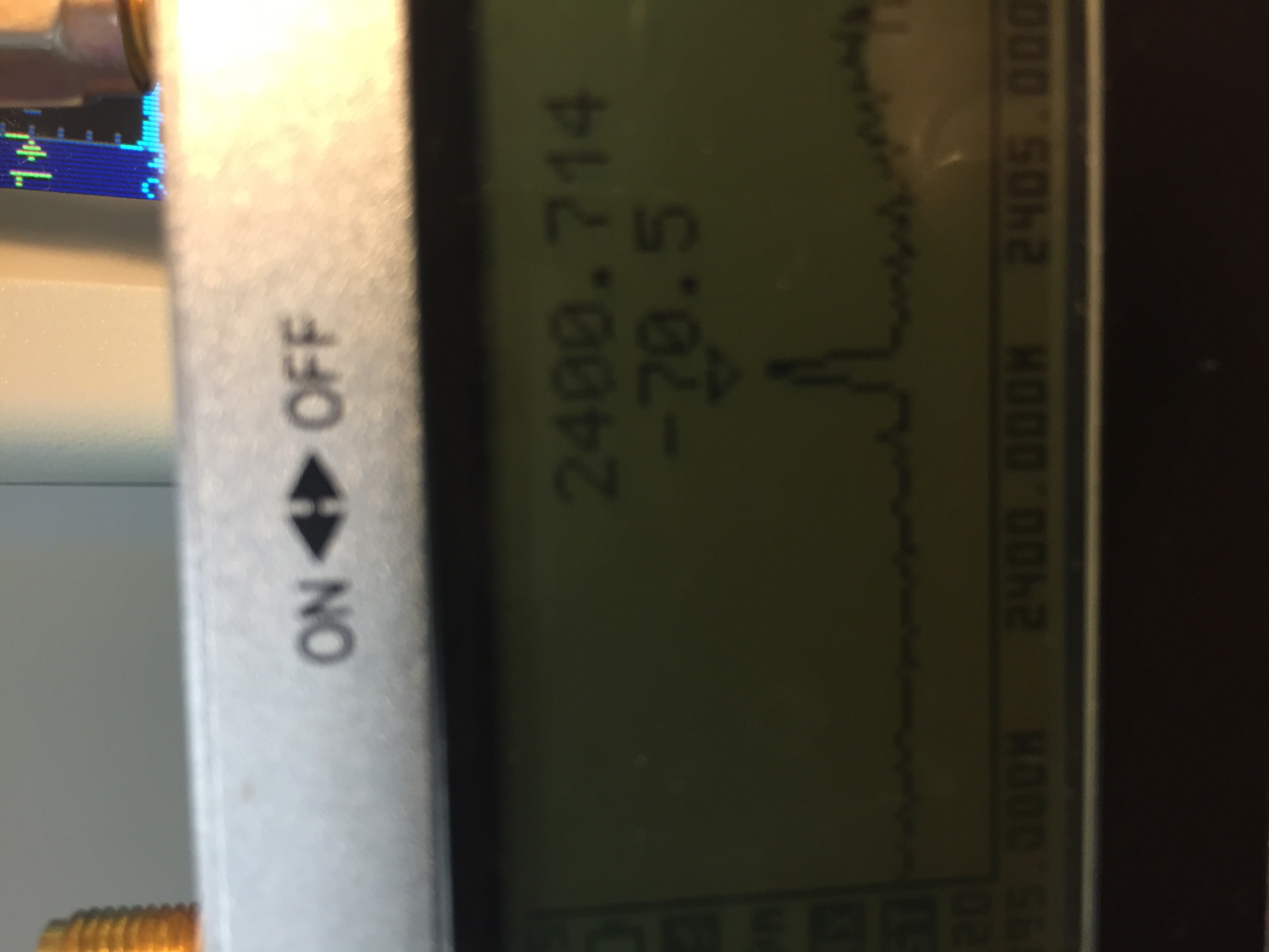
This is spectrum which I transmit data. I just checked the graph, not specific packet.
Thank you for your help! :)