This thread has been locked.

If you have a related question, please click the "Ask a related question" button in the top right corner. The newly created question will be automatically linked to this question.

CC110L writing RF registers

Other Parts Discussed in Thread: CC110L, CC1101

Hi,


I am using CC110L for a project and I have few questions about it. After going through datasheet and forum, the process of using it is resetting it first (using SRES) then write configuration registers to complete the initialization.

So,1) when writing the configuration registers, should Csn be low for one config reg (for both address and data) and go high. Then for another config register it goes low again and back high.


2) For every config register, what should we get on the MISO ? For example, if writing to IOCFG2 , address is 0x00 and data is say 0x06, so the format is-

Csn goes low,

MOSI-Write 0x00,0x06

MISO-? What should we get here?

Csn goes high.

3) It says in the datasheet that "Registers with consecutive addresses can be accessed in an efficient way by setting the burst bit (B) in
the header byte". So, config registers have consecutive address, we can use burst access here. So, what is the correct procedure for that? For example, IOCF2 address is 0x00 and data value is 0x06 and IOCFG1 is0x01 and data value is 0x07 and so on. So, if we set the burst access to one, will the format be -

Csn low.

MOSI-0x40, 0x06, 0x07 and so on.

MISO-??(What will be here?)

Csn high.
Kindly tell if this is the correct way.


Thanks,

Navneet

  • Hi

    1)

    You can write the register with single access, menaing that you send (address, data), (address, data), … CSn will be low for each address, data pair and go high in-between. If you are writing to many registers in a row you can do this using burst access. You then send the address of the first register you are accessing (with the burst bit set) and then you send data, data, data, ….. In this case CSn needs to below for the address and all the following data.

    2)

    The status byte described in table 5-2 is returned both when you send the address and the data. This is shown in figure 5-3. The values you receive depends on the state of you chip and you FIFO content. If you are in IDLE with empty FIFO, the status byte will be 0x00.

    3)

    This is correct. The status byte will be received for every byte written.

    Siri

  • Hi Siri,

    OK got it ! . I have interfaced CC110L with other micro controller. So, Is there any way to check our radio chip is initialized correctly. Like If I send some command , it gives back part number or something to make sure that SPI is working properly.

    Thanks,
    Navneet
  • Try to read out the VERSION register and see if you get 0x07 or 0x17
  • Hi,

    Yep, I got the SPI working. Thanks a lot !! :)
    But I have one more question. I have used CC110L as receiver.After resetting, writing to config registers,and setting it as a receiver (using 0x34), I receive the packet correctly for one time. After that for the second incoming packet, the contents get shifted .
    For example- transmitted packet (everytime) - 'a' 'b' 'c' 'd' 'e' 'f' 'g'
    packet 1 (7 bytes)- 'a' 'b' 'c' 'd' 'e' 'f' 'g'
    packet 2 (7 bytes)-'>' '!' ' 'a' 'b' 'c' 'd' 'e'

    It gets filled with some random values. So is there any way to reset the FIFO?

    Thanks,
    Navneet
  • If you send a different packet the second time ('1' '2' '3' '4' '5' '6' '7' as an example) what do you read from the FIFO then? I suspect that you don't read out the correct number of bytes.
  • Hi,
    Yep, now I am getting the correct packet but it just reads till 16 bytes. I am using variable packet length mode and i define the packet length as 0x0f. For example- In smartrf, I am sending- (in hex) 0f1122334455667788990011223344 (15bytes) and I receive data in an array(it is an array of 64 bytes) as-
    array[0]= 0xf //What is this value??
    array[1]=0xf //i got to understand that this is the length of the packet
    array[2]= 0xf //packet starts from here
    array[3]=0x11 //correct
    array[4]=0x22 //correct
    array[5]=0x33 //correct
    array[6]=0x44 //correct
    array[7]=0x55 //correct
    array[8]=0x66 //correct
    array[9]=0x77 //correct
    array[10]=0x88 //correct
    array[11]=0x99 //correct
    array[12]=0x00 //correct
    array[13]=0x11 //correct
    array[14]=0x22 //correct
    array[15]=0x33 //it is correct till here
    array[16]=0x5a //what is this value? is this the status byte which is appended at the end?(RSSI?) (It should have got values from the data packet i.e. 0x44)
    array[17]=0xab //same as above, (is this CRC byte??)
    array[18]=0xf
    array[19]=0x11
    array[20]=0x22
    array[21]=0x33
    array[22]=0x44
    array[23]='c'
    array[24]=0xac
    array[25]=0x12
    array[26]=0xa0
    array[27]=0x13

    and random values so on till array[63].

    Everytime I get the correct value till array[15]. Can you suggest if I am missing anything to read values from FIFO more than 16 bytes??

    Thanks,
    Navneet

  • You are not saying too much on how you get the data from the RXFIFO into your array. It could sound like you start copy the data from the wrong location. I assume you turn off the sequence number when sending from SmartRF Studio.

    The below shows how we do in in our example code:

     while(1)
      {
        // wait for packet received interrupt 
        if(packetSemaphore == ISR_ACTION_REQUIRED)
        {
            cc1101SpiReadReg(CC1101_RXBYTES,&rxBytesVerify,1);
            
            do
            {
              rxBytes = rxBytesVerify;
              cc1101SpiReadReg(CC1101_RXBYTES,&rxBytesVerify,1);
            }
            while(rxBytes != rxBytesVerify);
            
            cc1101SpiReadRxFifo(rxBuffer,(rxBytes));
            
            // check CRC ok (CRC_OK: bit7 in second status byte)
            if(rxBuffer[rxBytes-1] & 0x80)
            {
              // update packet counter
              packetCounter++;
            }
          
          // update LCD
          updateLcd();
          // reset packet semaphore
          packetSemaphore = ISR_IDLE;
          
          // set radio back in RX
          trxSpiCmdStrobe(CC1101_SRX);
          
        }
      } 
  • Hi,

    I wrote a code based on this code only but I am not using interrupts right now. I am polling the length of data from RX_BYTES status register and always get 16. I think that's the reason I can read till 16 bytes only. After that, I check for the RX overflow. If no overflow is there, I read the data packet from RX_FIFO . That data packet is array of 64 bytes where it gets filled up every time till first 16 bytes. What to do to read more than 16 bytes?

    I don't understand the value for first byte. It is a random value. I can see the transmitted packet starts from fourth byte till 16th byte. After that its all random.

    What is the purpose of adding sequence number? Yep, I had turned it off because I wanted to read the data packet from the first byte.

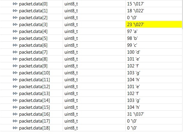
    Right now-I sent "abcdefghijkl" with "add seq number" turned on.

    I receive-

    Can you explain the packet.data[0] value and why I did not received "ijkl" ?

    Kindly help. Thanks and Regards,

    Navneet

  • Hey ,

    I am using same CC110L for communication . As you have mentioned , you are writing 0x00 ( register address ) 0x06 ( register value ) on MOSI , So do you enter ( 0x3E ) For Writing PATABLE address before sending register address and register in single mode ?

    Thank you .
    Regards,
    Sushrut Lagwankar.