This thread has been locked.

If you have a related question, please click the "Ask a related question" button in the top right corner. The newly created question will be automatically linked to this question.

CC115L GDO0 power-up

Other Parts Discussed in Thread: CC115L, CC110L, TEST2

Hello,

We are using the CC115L without any interrupts driven.
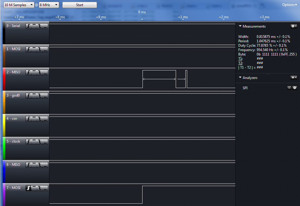
When tested upon power-up the GDO0 and GDO2 are active for a few uSec. 

  1. What should be done for production?
  2. Should we terminate the Pin 3,6 (GDO0, GDO2) to ground with resistor to minimize the current leak? 
  3. Is there a better solution?

Regards.
  • Hi,

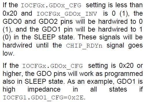
    Please refer to section 24 of CC110L Data sheet. The following is the description for your ready reference.

    Thanks,

    PM

  • Hi,

    I observed the Picture is missing. Please see the attached.

    Thanks,

    PM

  • Thank you for your replay.

    Following your replay I found the same documentation in the the CC115L.

    In the data sheet of CC115L section 5.16:

    47 (0x2F) - HW to 0 (HW1 achieved by setting GDOx_INV=1). Can be used to control an external PA.

    We set SMARTRF_SETTING_IOCFG0 and SMARTRF_SETTING_IOCFG2 to 0x2F => the GDOx_INV is in 0

    So why do we see more than 0.8 mili Seconds the GDO0 & GDO2 active?

    I have run a new test with the logic: logic leg 8 testing power up of device , logic leg 2 test GDO0 from the CC115L module:

    Is there something I'm not following from datasheet? 

    Please advice.

  • PM , could you kindly verify this or advice about steps that should be taken?
  • Hello,
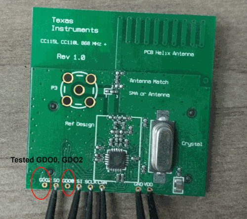
    The test was made by official module as in the pic attached:

    Can anyone advice on the matter?

    Can anyone try to replicate this please?

  • Hi,

    I sent your post to one Software team. They will verify and respond to it.

    Thanks,

    PM

  • Hi Avi,

    Can you please send me all register settings that you are programming in the device? You can also send me the .xml file.

    I am trying to replicate the issue you are seeing.

    Thanks,

  • Hello,

    Thank you for your replay.

    Register configuration:

    #define SMARTRF_SETTING_IOCFG2 0x2F 
    #define SMARTRF_SETTING_IOCFG1 0x2F 
    #define SMARTRF_SETTING_IOCFG0 0x2F 
    #define SMARTRF_SETTING_FIFOTHR 0x47
    #define SMARTRF_SETTING_SYNC1 0xD3
    #define SMARTRF_SETTING_SYNC0 0x91
    #define SMARTRF_SETTING_PKTLEN 0xFF
    #define SMARTRF_SETTING_PKTCTRL0 0x05
    #define SMARTRF_SETTING_CHANNR 0x00
    #define SMARTRF_SETTING_FSCTRL0 0x00
    #define SMARTRF_SETTING_FREQ2 0x23
    #define SMARTRF_SETTING_FREQ1 0x36
    #define SMARTRF_SETTING_FREQ0 0x27
    #define SMARTRF_SETTING_MDMCFG4 0xCA
    #define SMARTRF_SETTING_MDMCFG3 0xF8
    #define SMARTRF_SETTING_MDMCFG2 0xC3
    #define SMARTRF_SETTING_MDMCFG1 0x22
    #define SMARTRF_SETTING_MDMCFG0 0xF8
    #define SMARTRF_SETTING_DEVIATN 0x40
    #define SMARTRF_SETTING_MCSM1 0x30
    #define SMARTRF_SETTING_MCSM0 0x18
    #define SMARTRF_SETTING_RESERVED_0X20 0xFB
    #define SMARTRF_SETTING_FREND0 0x10
    #define SMARTRF_SETTING_FSCAL3 0xE9
    #define SMARTRF_SETTING_FSCAL2 0x2A
    #define SMARTRF_SETTING_FSCAL1 0x00
    #define SMARTRF_SETTING_FSCAL0 0x1F
    #define SMARTRF_SETTING_RESERVED_0X29 0x59
    #define SMARTRF_SETTING_RESERVED_0X2A 0x7F
    #define SMARTRF_SETTING_RESERVED_0X2B 0x3F
    #define SMARTRF_SETTING_TEST2 0x81
    #define SMARTRF_SETTING_TEST1 0x35
    #define SMARTRF_SETTING_TEST0 0x09
    #define SMARTRF_SETTING_PARTNUM 0x00
    #define SMARTRF_SETTING_VERSION 0x09
    #define SMARTRF_SETTING_MARCSTATE 0x01
    #define SMARTRF_SETTING_PKTSTATUS 0x00
    #define SMARTRF_SETTING_TXBYTES 0x00

    Kindly verify that IOCFGx (0,1,2) are at 0x2F

    cc115L__powerUp_GDO0_GDO2.xml
    <?xml version="1.0" encoding="ISO-8859-1"?>
    <!DOCTYPE configuration SYSTEM "C:/Program Files (x86)/Texas Instruments/SmartRF Tools/SmartRF Studio 7/config/xml/configdata.dtd"[]>
    <dcpanelconfiguration>
        <Devicename>CC115L</Devicename>
        <Description>Saved configuration data</Description>
        <registersettings>
            <Register>
                <Name>DEVIATN</Name>
                <Value>0x40</Value>
            </Register>
            <Register>
                <Name>FIFOTHR</Name>
                <Value>0x47</Value>
            </Register>
            <Register>
                <Name>FREQ0</Name>
                <Value>0x27</Value>
            </Register>
            <Register>
                <Name>FREQ1</Name>
                <Value>0x36</Value>
            </Register>
            <Register>
                <Name>FREQ2</Name>
                <Value>0x23</Value>
            </Register>
            <Register>
                <Name>FSCAL0</Name>
                <Value>0x1f</Value>
            </Register>
            <Register>
                <Name>FSCAL1</Name>
                <Value>0x00</Value>
            </Register>
            <Register>
                <Name>FSCAL2</Name>
                <Value>0x2a</Value>
            </Register>
            <Register>
                <Name>FSCAL3</Name>
                <Value>0xe9</Value>
            </Register>
            <Register>
                <Name>IOCFG0</Name>
                <Value>0x2f</Value>
            </Register>
            <Register>
                <Name>IOCFG1</Name>
                <Value>0x2f</Value>
            </Register>
            <Register>
                <Name>IOCFG2</Name>
                <Value>0x2f</Value>
            </Register>
            <Register>
                <Name>MARCSTATE</Name>
                <Value>0x01</Value>
            </Register>
            <Register>
                <Name>MCSM0</Name>
                <Value>0x18</Value>
            </Register>
            <Register>
                <Name>MDMCFG2</Name>
                <Value>0xc3</Value>
            </Register>
            <Register>
                <Name>MDMCFG3</Name>
                <Value>0xf8</Value>
            </Register>
            <Register>
                <Name>MDMCFG4</Name>
                <Value>0xca</Value>
            </Register>
            <Register>
                <Name>PA_TABLE0</Name>
                <Value>0x50</Value>
            </Register>
            <Register>
                <Name>PKTCTRL0</Name>
                <Value>0x05</Value>
            </Register>
            <Register>
                <Name>RESERVED_0x20</Name>
                <Value>0xfb</Value>
            </Register>
            <Register>
                <Name>RESERVED_0x29</Name>
                <Value>0x59</Value>
            </Register>
            <Register>
                <Name>RESERVED_0x2A</Name>
                <Value>0x7f</Value>
            </Register>
            <Register>
                <Name>RESERVED_0x2B</Name>
                <Value>0x3f</Value>
            </Register>
            <Register>
                <Name>TEST0</Name>
                <Value>0x09</Value>
            </Register>
            <Register>
                <Name>TEST1</Name>
                <Value>0x35</Value>
            </Register>
            <Register>
                <Name>TEST2</Name>
                <Value>0x81</Value>
            </Register>
        </registersettings>
        <dcpanel>
            <Property name="m_chkRegView" role="44">2</Property>
            <Property name="m_chkRfParameters" role="44">2</Property>
            <Property name="m_tabUserMode" role="37">1</Property>
            <Property name="m_easyModeSettings" role="33">-1</Property>
            <Property name="m_typicalSettings" role="33">-1</Property>
            <Property name="m_testFuncPanel" role="37">1</Property>
        </dcpanel>
        <rfparameters>
            <Property name="Xtal frequency" role="46">26.000000</Property>
        </rfparameters>
        <conttx>
            <Property name="m_rbtModulated" role="45">1</Property>
            <Property name="m_rbtUnmodulated" role="45">0</Property>
            <Property name="m_cmbDataFormat" role="46">-1</Property>
            <Property name="m_chkFreqSweep" role="44">0</Property>
            <Property name="m_chkChanSweep" role="44">0</Property>
        </conttx>
        <packettx>
            <Property name="m_edtPayloadSize" role="42">12</Property>
            <Property name="m_edtPacketCount" role="42">3</Property>
            <Property name="m_edtPacketCountEsy" role="42">100</Property>
            <Property name="m_edtRandomPacketData" role="42">29 23 be 84 e1 6c d6 ae 52 90 49 f1 f1 bb e9 eb b3 a6 db 3c 87 0c 3e 99 24 5e 0d 1c </Property>
            <Property name="m_edtPacketData" role="42">0B 00 04 00 04 00 00 00 00 09 01 01</Property>
            <Property name="m_edtAccessAddress" role="42"></Property>
            <Property name="m_edtDeviceAddress" role="42"></Property>
            <Property name="m_chkAddSeqNbr" role="44">0</Property>
            <Property name="m_chkInfinite" role="44">0</Property>
            <Property name="m_chkInfiniteEsy" role="44">0</Property>
            <Property name="m_rbtRandom" role="45">0</Property>
            <Property name="m_rbtText" role="45">0</Property>
            <Property name="m_rbtHex" role="45">1</Property>
            <Property name="m_chkAdvanced" role="44">0</Property>
        </packettx>
        <commandpanel>
            <Property name="m_chkInsertLength" role="44">0</Property>
            <Property name="m_edtTxFifo" role="42"></Property>
            <Property name="m_edtRxFifo" role="42"></Property>
            <Property name="m_cmbInstrInput" role="46">-1</Property>
        </commandpanel>
    </dcpanelconfiguration>
    

  • FI hello,

    Any progress?

    have you got the same jumps upon power-up?

    Would you recommend different IOCFG configurations to prevent that behavior?

    Regards. 

  • Why is it important to avoid GDO0/ GDO2 going high at start-up?
  • Ter hello,

    Thank you for your replay.
    I highly value your posts & insights so I do my best to answer :)

    Our usage would need for minimal power wastes.
    We need to connect GPIO 0/2 to ground (reasons aside since aren't important).
    If on boot time we get high on them for several mSec we simply waste power.
    Our solution can be turned on/off several times during lifetime (it is our users decision).
    Overall it will still not be "allot" but if we can avoid wasting power we are interested in doing so.
  • Why does this cause a power waste? The load on the pins is normally capacitive and one toggle will cause very little power drain. I assume you power cycle the CC115L on an infrequent basis.

    The output value on the DIOs are set in the end of the start-up sequence. While the VDD is ramped up the output state could change dependent on when the BOD/POR change state.
  • Thank you for your replay.

    As you wrote it will cause little power drain.. we would like to eliminate that (even if its very small).
    I do understand you point about the initialization sequence but finding it kind of "yes it's broken but .. it's not that important for you."

    If there is a workaround/ solution for that please let us know about it.
    If it is only happening in our module please let us know.
  • When the chip is starting up the states internally will change according to where in the start-up sequence the chip is. Also the reset value for GDO2 is set to CHP_RDYn and for GDO0 to CLK_XOSC/192 meaning that both will be high/ alternating before writing a different setting to this registers.

    Trying to tie the outputs with resistors will increase the current consumption.

    Do you have a number on how much current this contribute in your system? My first though is that this number will be much lower than the leakage current in the system looking at the average current in the system.