This thread has been locked.

If you have a related question, please click the "Ask a related question" button in the top right corner. The newly created question will be automatically linked to this question.

Reset loop on CC13xx with high battery resistance

Other Parts Discussed in Thread: CC1350, CC2640, CC1310

Hi, we have a case where a CC1350 is powered from a small battery. At low temperatures, the impedance of the battery may be quite high. To work with this, we have a capacitor in parallel to lower the impedance of the power supply, and then put CC1350 in Standby most of the time. We make sure to recharge the capacitors enough between bursts of activity such that in theory, the system should not go in brown-out.

However, for various reasons like corner cases not handled properly by our firmware, the chip may try to use more charge than can be delivered from the capacitor and go into brownout. This would be OK if we could recover from it, however, the chip seems to get stuck in an infinite reset loop where it draws large amounts of current, quickly draining the battery beyond salvage. It seems that brownout triggers a reset that allows the voltage to rise a bit, but that the chip immediately after releases reset and tries booting, causing the power to drop again etc.

Is there a way to configure a reset delay? Such that when a brown-out occurs, reset is held for some time to allow the power system to recover? Or other suggestions for how to work around this problem?

Thanks, Pål Øyvind

  • Basically you need to check if the last reset was caused by a BOD and if that is the case keep the chip in Standby for some time to ensure that the voltage is sufficiently high. On CC2640 we have done this with a task in some test code.
  • Thanks TER, but the problem is that the chip never reaches a point where it can execute code to check if the reset reason was a BOD and enter Standby before the voltage is so low that BOD triggers again...
  • Do you have a power profile showing the relation between current and voltage when you are in this loop?

    How large is the cap on VDDS and VDDR in your design? (In other word do you follow the ref design)
  • Hello TER,

    The caps on my design are different from the ref design (quite a lot more capacitance on VDDS), but I don't think that is the root cause of this issue.

    I ran a test application on the ref design (CC1310 EM) to illustrate the problem. This application basically tries to find out if the last reset was a brownout, and if it was, go to Standby as fast as possible and stay there. If the reset reason was not a brown-out, just blink a LED.

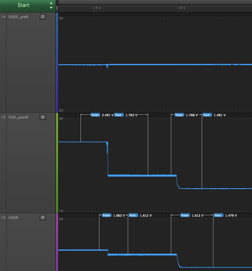
    Then I boot into this application with a 2.5V supply. In series with the supply, I have put a 1k series resistor to simulate a cold battery, but i keep the resistor shorted to boot into the LED-blinking code. Around 4s in the plots below I remove the short to force a brown-out. As you can see from the plots, the chip goes in brown-out, and the power drawn through the 1k resistor stays on the order of 1mA such that the circuit never recovers. Standby is never reached.

    What happens around 5s is unknown to me, it starts drawing even more current... Can you explain?

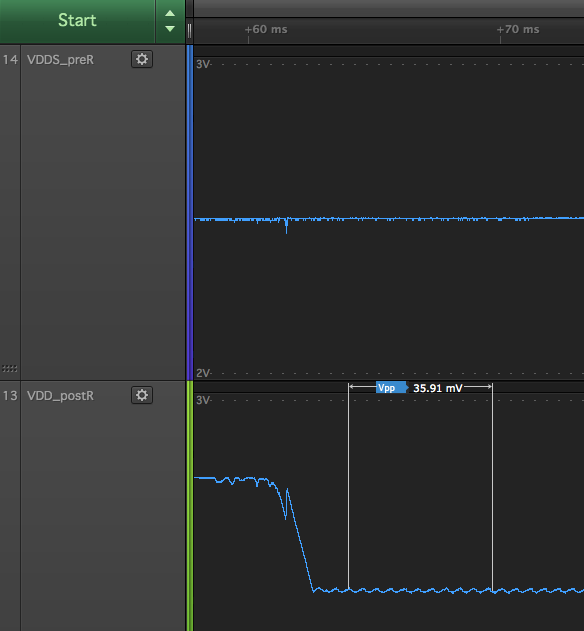
    If we zoom in on the details, we see the contours of a loop that takes 560us each cycle (no doubt dependent on R and C), where the voltage starts to recover, but then reset release causes it to drop into brown-out again:

    Now, if there only was a way to enforce a longer reset hold time or a lower current consumption in this "mode"...

    void main(void)
    {
      uint32_t resetSource = SysCtrlResetSourceGet();
      if (resetSource==RSTSRC_VDD_LOSS || resetSource==RSTSRC_VDDR_LOSS || resetSource==RSTSRC_VDDS_LOSS)
      {
        //Go down in Standby as fast as possible to see if we at all can reach a low-power state without brown-out again
        GoToStandbyForever();
      }
    
      SysCtrlPowerEverything();
    
      IOCPinTypeGpioOutput(IOID_25);
      while(1)
      {
        //Blink LED 1
        CPUdelay(4000000);
        GPIO_toggleDio(25);
      }
    }
    
    void GoToStandbyForever(void)
    {
      //Ripped from TI-RTOS, scratched down for demo purpose
    
      IntMasterDisable();
    
      /* 1. Freeze the IOs on the boundary between MCU and AON */
      AONIOCFreezeEnable();
    
      /* 2. If XOSC_HF is active, force it off */
      if(OSCClockSourceGet(OSC_SRC_CLK_HF) == OSC_XOSC_HF) {
        OSCHF_SwitchToRcOscTurnOffXosc();
      }
    
      /* 3. Allow AUX to power down */
      AONWUCAuxWakeupEvent(AONWUC_AUX_ALLOW_SLEEP);
    
      /* 4. Make sure writes take effect */
      SysCtrlAonSync();
    
      /* now proceed to transition to Power_STANDBY ... */
    
      /* 6. Gate running deep sleep clocks for Crypto and DMA */
      PRCMPeripheralDeepSleepDisable(PRCM_PERIPH_UDMA);
      PRCMPeripheralDeepSleepDisable(PRCM_PERIPH_CRYPTO);
    
      /* 7. Make sure clock settings take effect */
      PRCMLoadSet();
    
      /* 8. Request power off of domains in the MCU voltage domain */
      PRCMPowerDomainOff(PRCM_DOMAIN_RFCORE | PRCM_DOMAIN_SERIAL | PRCM_DOMAIN_PERIPH | PRCM_DOMAIN_CPU);
    
      /* 9. Request uLDO during standby */
      PRCMMcuUldoConfigure(true);
    
    
      /* 10. If don't want VIMS retention in standby, disable it now... */
    
      /* 10.4 Now disable retention */
      PRCMCacheRetentionDisable();
    
      /* 11. Setup recharge parameters */
      SysCtrlSetRechargeBeforePowerDown(XOSC_IN_HIGH_POWER_MODE);
    
      /* 12. Make sure all writes have taken effect */
      SysCtrlAonSync();
    
      /* 13. Invoke deep sleep to go to STANDBY */
      PRCMDeepSleep();
    
      //Will not return from this code
      while(1);
    }


  • Basically you either have to have a battery that could handle the boot current (1 kohm would mean that you are on the BOD limit with less than 1 mA current draw) or you have to have an external supply supervision circuit that keep the CC1310 in reset until the voltage is high enough to avoid the BOD reset loop.
  • Thanks TER, 
    Not what I wanted to hear, but what I anticipated. :) Suggestion/feature request for future silicon/future devices: Some way to program the reset release delay. (Or an adaptive reset delay that incorporates some kind of slow lossy integrator that gets a kick every reset such that frequent successive resets increases the delay.)