This thread has been locked.

If you have a related question, please click the "Ask a related question" button in the top right corner. The newly created question will be automatically linked to this question.

CC1125: CC1125 output network

Part Number: CC1125
Other Parts Discussed in Thread: CC1120EMK-169, CC1120

Hello.

I'd like to know if an application note (or an explanation) about the design of the passive network used at CC1125 output is available.

 I'm having problems with the output spectrum in the 169MHz band.

Thank you in advance.

Best regards,

Peppe

  • We don't have not but:
    - We can take a look at your schematic
    - Please upload plot(s) of what you are seeing. What sort of problems with the spectrum?
    (Is this un-modulated, modulated, sending packet, which settings etc)
  • Hi TER, thank you very much for your interest.

    We are using TI CC1125 transceiver with Skyworks SKY65367-11. We used SKY65367-11 + CC112X/CC120X Reference Design Italian v1.0 (swrr111) as a reference for the schematic.

    As you can see from the attached picture, the output spectrum has two big side lobes that fail ETSI EN 300 220-1 masks. I'd like to know if such an issue could be caused from e.g.:

    • board schematic/layout (I used the same components value of the reference, but different stack-up);
    • CC1125 configuration (I am using SmartRF Studio 7 v. 2.6.0 configuratio).

    Do you have any suggestions?

    Thank you in advance.

    Best regards,

    Peppe

  • I would assume a combination of schematic and layout. I can review both (schematic as pdf, layout as gerber) to see if anything pops up. If you don't want the files to be public on the forum you can send a friend request.

  • Hello TER.

    Thank you very much for your willingness to review our design files, but I cannot provide them at the moment.

    Anyway, after further measurements, I'd say it isn't an issue with our design.

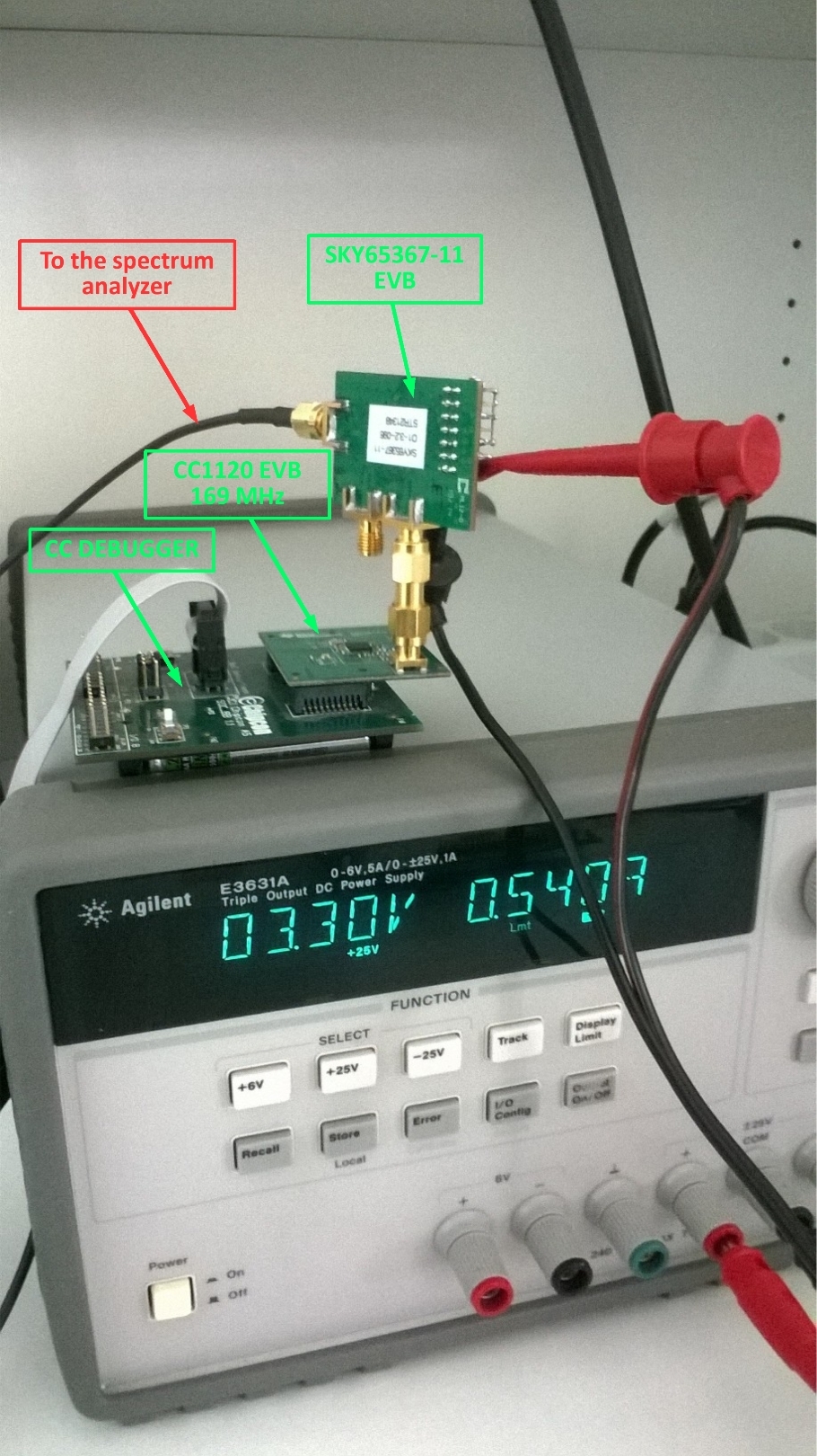
    We repeated same measurements using CC1120 evaluation module @ 169 MHz (CC1120EMK-169) connected to SKY65367-11 evaluation board through a SMA-SMA connector. CC1120EMK-169 module is powered by its two AA batteries whereas SKY65367-11 board is powered using an external power supply (I tried with battery too and didn't observe any change). In the attached picture, you can see that the side lobes issue exists as in our board. The shape of the spectrum is very similar. Do you have any spectrum acquisition using SKY65367-11 to compare with my measurements?

    Thank you in advance.

    Best regards,

    Peppe

  • Test the output spectrum of just the tranceiver and this should be fine. The problem could be related to the powering of the SKY65367-11.

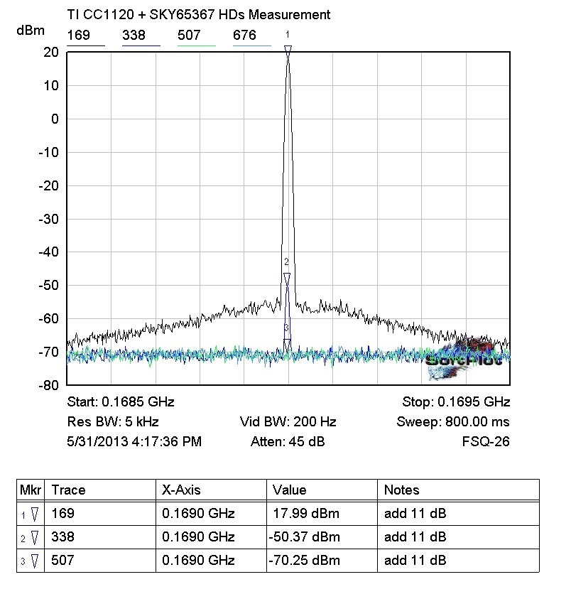
    See attached pic for CC1120 SKY65367 at 169 MHz.

    //Richard

  • If it is the powering of SKY 65367 then see attached app note from Skyworks

    SKY65367&SKY66100_App Note_203047B.pdf

  • Good morning.

    I'm Tommaso, a colleague of Peppe. I'm testing the board introduced by Peppe in the previous posts.

    I have used the following parameters in the measurements:

    1. RBW = 100 kHz

    2. VBW = 30 kHz

    3. START FREQUENCY = 30 MHz

    4. STOP FREQUENCY = 220 MHz

    5. I add an external 20 dB attenuator

    The acquired spectrum is the following:

    As anticipated by Peppe, the same results are obtained using CC1120 EVB and SKY65367 EVB. The measurement setup is the following:

    If I use your measurement parameters I get a clean spectrum too.

    Using my parameters, the side bands don't allow to pass ETSI EN 300 220-1 V2.4.1 "Unwanted emissions in the spurious domain" mask (paragraph 7.8.2.1). Have you ever noticed this aspect? Am I doing something wrong? I have the same problems with my board and with EVB boards.

    Thanks in advance.

    Best regards.

    Tommaso

  • Note that the current version of EN300 220 is 3.1.1.

    I haven't done any measurements on this my self. From the plot it looks like the spectrum is overloaded since the peak goes outside the grid. Is that the case? Do you see the same with different attenuation, ref level etc?
  • Side lobes appear regardless external attenuation and reference levels.
    I used an external 20 dB attenuator. Spectrum analyzer max input power is +30 dBm.
    If I connect +15 dBm CC1120 ouput power without SKY65367 to spectrum analyzer, side lobes don't appear.
  • In this case it sounds like the SKY introduces the sidelobes. You can also test with a signal from a signal generator to the SKY EVB and see if you still see the sidelobes. I don't have the SKY EVB available so I'm not able to check. The SMA that is open on the board, should that be open or terminated?
  • Skyworks support replied me that connecting an analog signal generator to SKY65367, the noise floor was lower and pass ETSI mask. The problem is that I can't connect an analog signal generator, I have to use CC1125!!! Could it not be that CC1125 output signal has amplitude variation (not visible without power amplifier) and then these variations are amplified causing sidelobes? What do you think about that?
    Tha SMA open in te board is RX channel of SKY65367. When I took the photo, I forgot to mount 50 ohm load.
  • See plot Richard posted in May in this thread: CC1120 + SKY (CC1120 and CC1125 has fairly equal phase noise and if a difference is that CC1125 should be better) looks good on our reference design. I have to check with Richard when he gets back from vacation if we have the SKY EVM you are testing with.

    Could you post the plot you got with SG + SKY EVM? Is it possible for you to check with a different spectrum in case the spectrum contributes to the result?