This thread has been locked.

If you have a related question, please click the "Ask a related question" button in the top right corner. The newly created question will be automatically linked to this question.

RTOS/LAUNCHXL-CC1310: LP wouldn't enter standby mode

Part Number: LAUNCHXL-CC1310

Tool/software: TI-RTOS

Hi,

  I'm trying to optimize current consumption of my application, and I doubt my LAUNCHXL-CC1310 is not entering standby mode. Even though my sleep() calls are for multiple seconds. Current consumed is around 3mA.

I ran pinStandby application without any modification, even that too is showing around 3mA current consumption when LEDs are off.

I'm measuring current using a series resistor of 4Ohms, as well with 18Ohms and an oscilloscope. Can this measuring method be so wrong??

Code is given below. All I'm using is EasyLink driver and GPIOs for input as well as output.

int main(void)
{
    Semaphore_Params semParams;
    /* Call driver init functions. */
    Board_initGeneral();


#ifdef DEBUG
    UART_init();
#endif


    /* Open LED pins */
    pinHandle = PIN_open(&pinState, pinTable);
    if(!pinHandle) {
        System_abort("Error initializing board LED pins\n");
    }

    /* Construct a Semaphore object to be use as a resource lock, inital count 1 */
    Semaphore_Params_init(&semParams);
    Semaphore_construct(&uartSemStruct, 1, &semParams);

    /* Obtain instance handle */
    uartSemHandle = Semaphore_handle(&uartSemStruct);

    txTask_init(pinHandle);

    /* Start BIOS */
    BIOS_start();

    return (0);
}

static void rfEasyLinkTxFnx(UArg arg0, UArg arg1)
{
    uint32_t result;

    // enable battery monitor enable
    AONBatMonEnable();

    //radio init

   ret = EasyLink_init(EasyLink_Phy_625bpsLrm);
    ret = EasyLink_setFrequency(867000000);
    ret = EasyLink_enableRxAddrFilter((uint8_t *) (&addrFilter), 4, 1);

#ifdef DEBUG
    log_init();
#endif


    crypto_init();


    while(1) {

            batt_voltage = senseBatteryVoltage();
            sensor_scan();
            result = send_status();

           Task_sleep(4 * 100000);
    }

}

Any suggestions are welcome.

  • Instead of depending on Task_sleep(), made call directly to

    Power_sleep(PowerCC26XX_STANDBY);

    Even then the current draw is around 3mA. :(
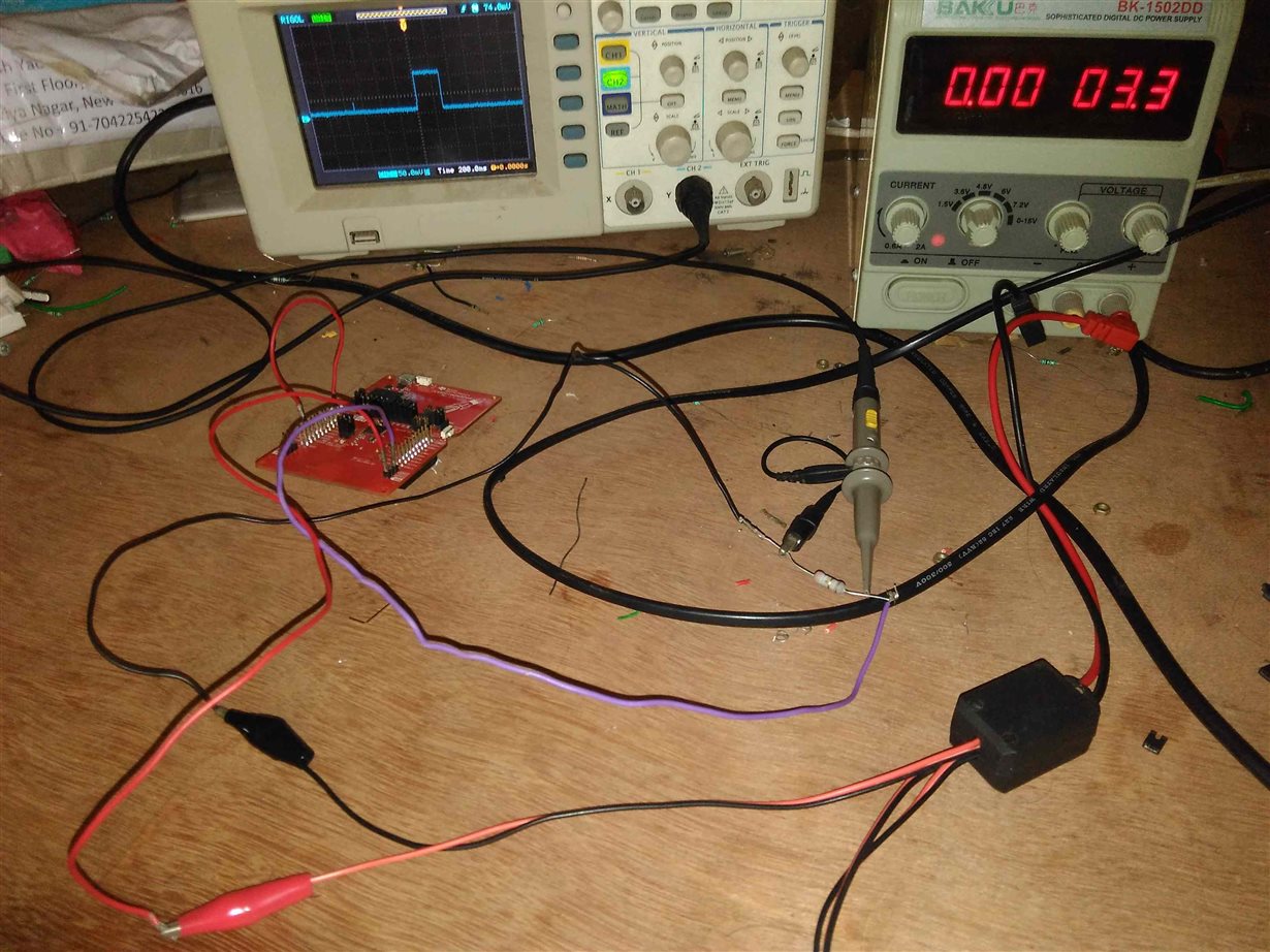
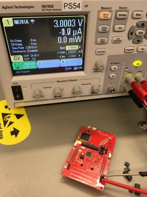
  • Could you post a picture showing how you are measuring the current consumption (including the board you are measuring on?)
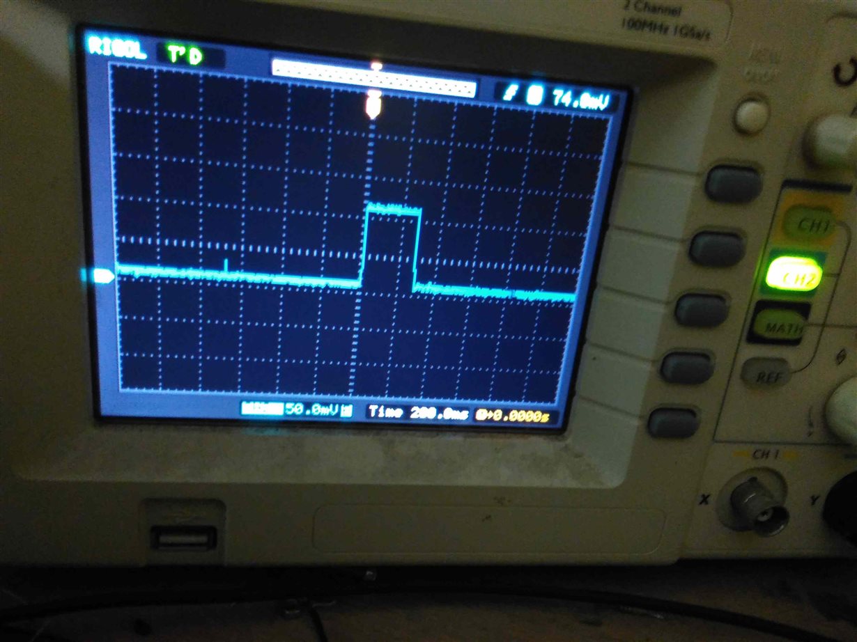
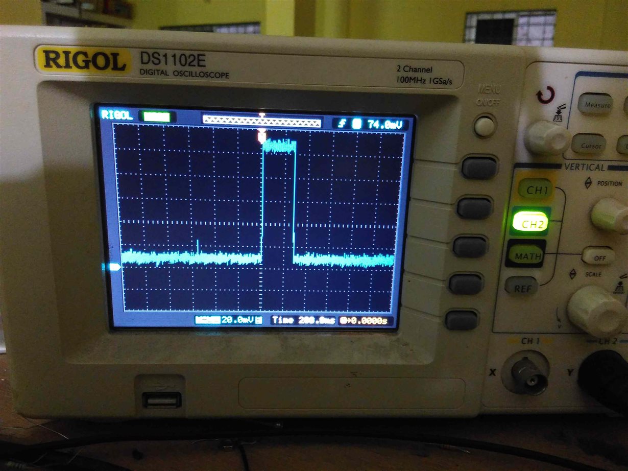
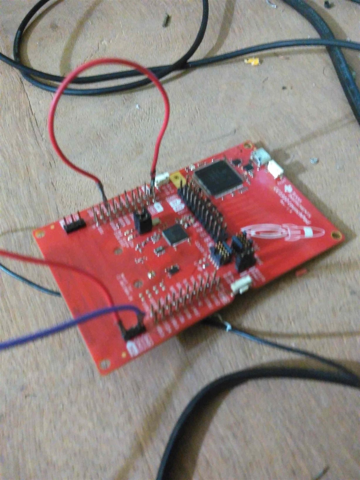
  • Pic 1: +ve of bench supply to 3.3V pin on LP. -ve of bench supply to a 4Ohm resistor and resistor to GND pin on LP. Oscilloscope connected to both sides of the resistor.

    Pic 2: Scope showing higher floor with one peak sending a 16 byte packet in LRM mode at +14dBm. Average floor is at ~10mV

    Pic 3: Better scope granularity.

    Pic 4: I removed all the jumpers between debugger and mcu. Weird enough, current consumption hiked to almost double. In earlier pictures all but 5V, 3.3V jumpers are retained.

    Pic 5: That jumper on 8th pin is for input sensing. Pin is connected to 3.3V pin.

  • Why are you calling crypto_init(); without using crypto?

    The latest picture looks like a correct setup, you have to remove all jumper to avoid current draw from LEDs and the debugger.
  • Hi, regarding you statement:
    "I ran pinStandby application without any modification, even that too is showing around 3mA current consumption when LEDs are off."

    The fact that you are measuring 3mA with the standard example with LEDs OFF tells me that there is something not correct with your measurement. Here I assume other jumpers are off as well.

    I tested the latest pinStandby example this morning, and measured  various scenarios.
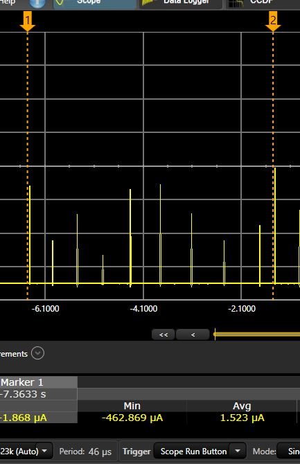
    With LEDs enabled I measured ~1.1uA between the LEDs toggling (standby period):

    When removing LED jumpers, I measure 1.5uA between the pin toggling, I also observe that the number of recharge pulses has increased thus giving a slightly elevated number compared to the last measurement:

    But we are still in the uA area, while you measure 3mA...

    As a first step you should try to measure the standard pinStandby example according to these numbers.

    My setup:

  • We're encrypting the packet using AES hw module right before sending packet in a function.
  •   I do have an interesting observation.

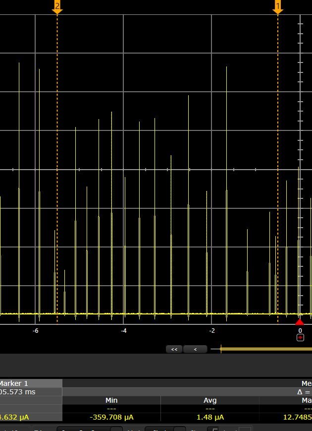
    To have a common reference with you, I ran the pinStandby application and scope pics are not very different. But I changed the LP and tested pinStandby again. Everything else being same, scope plot is recognizably different. Multimeter too is showing 300microVolts instead of 8mV across 4Ohm resistor.

    Where as first LP's plots are

  • Can it be that level shifters are drawing power? I changed the jumper to "External Pwr". I can see the drop in current.
    What is the correct position for this jumper to be in? when we are powering from external power, and not using xds at all.
  • Sorry, I meant I removed the jumper from "External Pwr" and current dropped to near zero. May be I have to blame my current consumption to this jumper.
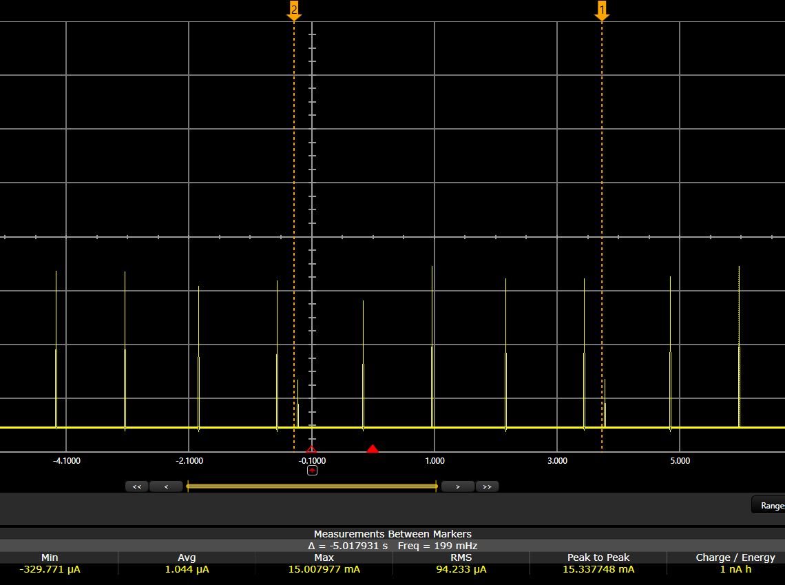
  • Hi, yes remove that jumper as well. I tested with and without XDS Power with the following result:

    With jumper:

    Without jumper: