This thread has been locked.

If you have a related question, please click the "Ask a related question" button in the top right corner. The newly created question will be automatically linked to this question.

CC1175: CC1175 with EXT_XOSC frequency off by

Part Number: CC1175
Other Parts Discussed in Thread: CC2541, CC1120,

I'm using the following configuration:

{CC112X_FREQ2, 0x6C}, //(0x2f0c) frequency configuration [23:16]

{CC112X_FREQ1, 0x80}, //(0x2f0d) frequency configuration [15:8]
{CC112X_FREQ0, 0x00},

That should set the carrier to 868.000000

The measured RF frequency is 934Mhz.  I'm using an external clock verified at 32Mhz.  The clock is generated by a pin on the CC2541.  Is there a register setting to use an external oscillator?  Would I have to modify the XOSC registers from their default?

Thank You

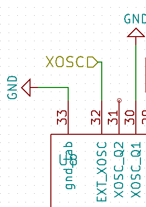
  • - The chip auto detect that you have connected something to the EXT_XOSC pin.
    - Have you run a SCAL strobe or ensured VCO calibration some other way?
    - For RF you need a high quality clock source. Using CC2541 as a clock source will not be the best option.
  • yes, Would I need to rerun SCAL before transmission if the radio was powered off? The CC2541 uses very precise timing for bluetooth operations.

    trxSpiCmdStrobe(CC112X_SCAL);

    // Wait for calibration to be done (radio back in IDLE state)
    do {
    cc12xxSpiReadReg(CC112X_MARCSTATE, &marcState, 1);
    } while (marcState != 0x41);

    // Put radio in powerdown to save power
    trxSpiCmdStrobe(CC112X_SPWD);
  • Hi

    How do you set the clock out from CC2541?

    What kind protocol you used on CC2541, BLE or Proprietary?

    If BLE protocol, you should  make sure the CC2541 not going to sleep. Because BLE protocol will going to sleep when CC2541 IDLE.

    BR,

    Jack

  • If CC1120 has been in power down, the registers that don't have retention has to be set again and a new SCAL strobe has to be issues.

    If you generate the clock from CC2541 the clock will have jitter causing phase noise. Have you checked that the spectrum looks OK (disregard the frequency error)?
  • I'm using P0_6

    P0SEL |= 0x40; //peripheral select timer1
    T1CTL = 0;
    T1CTL |= TIMER_TICK_1 | TIMER_MODE_UD;
    T1CCTL1 = 0;
    T1CCTL4 |= TIMER_TOGGLE_OUTPUT_ON_COMPARE | TIMER_MODE_COMPARE;
    T1CC0H= 0x00;
    T1CC0L = 0;
    T1CTL |= TIMER_START;

    I'll inspect jitter.  I noticed on the oscilloscope it looked like a sine wave and not a square wave.

  • It's using BLE but it's in a while(1) loop
    I'm setting the clock by the following:
    P0SEL |= 0x40; //peripheral select timer1
    T1CTL = 0;
    T1CTL |= TIMER_TICK_1 | TIMER_MODE_UD;
    T1CCTL1 = 0;
    T1CCTL4 |= TIMER_TOGGLE_OUTPUT_ON_COMPARE | TIMER_MODE_COMPARE;
    T1CC0H= 0x00;
    T1CC0L = 0;
    T1CTL |= TIMER_START;

    I haven't changed anything in CLKCONSTA,SLEEPCMD,or SLEEPSTA
  • Hi,

    Did you check the 32MHz clock accuracy and stability through an oscilloscope? 

    I'm not sure the accuracy and stability is good enough if you use time1 and compare mode to create clock source while the BLE stack is running.

    Just like TER suggested in the first reply, using CC2541 as a clock source is not the best option. 

    Maybe you can test another clock source (like TCXO) to make sure the issue on CC1175 is from code or clock source.

    BR,

    Jack

  • I'll do that.  Thanks all