This thread has been locked.

If you have a related question, please click the "Ask a related question" button in the top right corner. The newly created question will be automatically linked to this question.

CCS/CC1310: How to use multiple-buffered output data exchange in the Sensor Controller Studio

Part Number: CC1310

Tool/software: Code Composer Studio

Hi all,

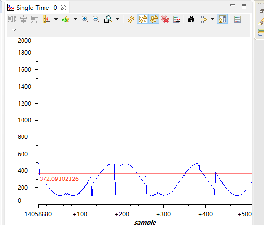
I met with some difficulties in using Sensor Controller Studio. I want to use the Sensor Controller Studio implement multiple continuous sampling by multiple ADC channels. In fact, there is no problem to run the program in the SCS,and sampling data is continuous . But when I put the process integrated into the CCS, when I put the sce ADC sampling data read out, found that is not a continuous waveform.So whether can go to solve this problem by  multiple-buffered output data exchange .

  • Hi, can you try to rephrase your question, I don't understand what the issue is.
    Are you saying that the ADC is not sampling the correct value? If so, can you try to sample without the input scaler enabled by calling adcDisableInputScaling(); before enabling the ADC (but careful: with the InputScaling disabled you can damage the ADC if voltage levels are too high).

  • Hi FredG,

    I think the ADC is  sampling  correct value.I use the ADC sampling a sine wave, but samples values to restore the waveform is not continuous,like this:

    This show is my by CCS reads data in the SCE,obviously lost a lot of time point data.

    I am setting the IO  level flip  to display the state of the ADC sampling found that sampling without interruption, as follows:

    So I doubt is that the reading data from the CCS is wrong,Or whether I am reading the sce of the output buffer by CCS will interrupt the ADC sampling. So i want to use the multiple-buffered output data exchange in the Sensor Controller Studio to  improve this situation.
    In the SCS code is as follows,by generating two interrupt to notify CCS to read data:
    // Enable the ADC
    
    adcEnableSync(ADC_REF_FIXED, ADC_SAMPLE_TIME_2P7_US, ADC_TRIGGER_MANUAL);
    
    
    // Sample the sensor
    U16 n = output.head;
    //U16 m = output.count;
    
    gpioSetOutput(cfg.pAuxioOLedCtrl[0]);
    adcSelectGpioInput(cfg.pAuxioASensorOutput[0]);
    adcGenManualTrigger();
    adcReadFifo(output.pSamples[n]);
    utilIncrAndWrap(n, BUFFER_SIZE; output.head);
    
    n = output.head;
    adcSelectGpioInput(cfg.pAuxioASensorOutput[1]);
    adcGenManualTrigger();
    adcReadFifo(output.pSamples[n]);
    utilIncrAndWrap(n, BUFFER_SIZE; output.head);
    utilIncrAndWrap(output.count, BUFFER_num; output.count);
    state.halffull = 0;
    state.full = 0;
    gpioClearOutput(cfg.pAuxioOLedCtrl[0]);
    
    if(state.a==1){
        if(output.count>=64){
            if(output.count<95){
            state.halffull =1;
            fwGenQuickAlertInterrupt();
            gpioSetOutput(cfg.pAuxioOLedCtrl[1]);
            state.a = 0;
            state.b = 1;
            }
        
        }
    }
    
    if(state.b==1){
        if(output.count < 32){
            state.full = 1;
            fwGenQuickAlertInterrupt();
            gpioClearOutput(cfg.pAuxioOLedCtrl[1]);
            state.b = 0;
            state.a = 1;
        }
        
    }


    // Disable the ADC
    adcDisable();
    
    // Schedule the next execution
    fwScheduleTask(1);

    In the   code is as follows:

    static void taskAlertCallback(void)
    {
        int k= 0;
        scifClearAlertIntSource();
        if((scifTaskData.adcDataLogger.state.halffull == 1))
        {
        for(k=0;k<64;k++)
        {
            RxBuffer[k] = scifTaskData.adcDataLogger.output.pSamples[k*2];
            RxCount[k] = scifTaskData.adcDataLogger.output.pSamples[k*2+1];
        }
    
        }


        if((scifTaskData.adcDataLogger.state.full == 1))
        {
            int i = 0;
            for(i=0;i<64;i++)
            {
                RxBuffer[i+64] = scifTaskData.adcDataLogger.output.pSamples[i*2+128];
                RxCount[i+64] = scifTaskData.adcDataLogger.output.pSamples[i*2+128+1];
     
            }
         //   scifTaskData.adcDataLogger.state.full = 0;
    
        }
    
        scifAckAlertEvents();
    }
    

  • Ok, can you attach the CCS project? I would like to reproduce what you are seeing on my bench.

  • Ok thanks, will have a look at it.
    1. Could you also provide the SCS project, as the project file is missing in CCS.
    Just a comment in general. The ADCbuf driver has not been optimized for doing time muxed sampling of different pins, it has to close the ADC resource before reassigning to another DIO, then do a re-init and an open of the resource again- hence it could explain the issues you are seeing here (timing).
    2. If I understood you, you tried the project is SCS, and the graph in the Task Testing section looks ok, right?
    3. Can you briefly explain what you are trying to do with this application? Maybe we can work out another approach...

  • Hi FredG,

    Thank you very much for your quick reply.

    1. Yes,you are right,the graph in the Task Testing section looks ok in SCS.

    2. I want to continuous acquisition of multiple channels of ADC at the same time,and through CC1310's radio  to sent out, the most important thing is that the sampling can't be interrupted.This is similar to the single channel  continuous acquisition mode by use ADCBuffer in CCS.

    The SCS project:

    adc_data_logger_launchpad.rar

    Thank you again for your help.And i have a question, ADC channel switching time should not be too long?