This thread has been locked.

If you have a related question, please click the "Ask a related question" button in the top right corner. The newly created question will be automatically linked to this question.

Linux/CC1101: - Not Get any response from the sub-ghz cc1101 module

Part Number: CC1101

Tool/software: Linux

Hi,


I have develop cc1101 driver in linux. When I will try to receive data from configuration register then get the 0x7h value in all the time.

Below are snap of my code.

Reference: github.com/.../CC1101SocketDriver

uint8_t Spi::readSingleByte(const uint8_t address, uint8_t& value) {

        static const int LEN = 2;      
        uint8_t tx[LEN] = {0x80 | address, 0x00};
        uint8_t rx[LEN];

        struct spi_ioc_transfer tr;    
        memset(&tr, 0, sizeof tr);     

        tr.tx_buf = (unsigned long)tx;
        tr.rx_buf = (unsigned long)rx;
        tr.len = LEN;
        tr.speed_hz = this->speed;     
        tr.bits_per_word = this->bits;

        int rc = ioctl(this->fd_spi, SPI_IOC_MESSAGE(1), &tr);
        if (rc < 0) {
                perror("SPI single byte read failed");
                abort();
        }

        value = rx[1];

        DateTime::print();
        printf("read single byte address=0x%.2X status=0x%.2X value=0x%.2X\n", address, rx[0], value);

        // CHIP_RDYn (Bit 7)
        // Stays high until power and crystal have stabilized.
        // Should always be low when using the SPI interface.
        assert((rx[0] & 0x80) == 0);   

        return rx[0];
}

  • Could you post a plot of the SPI lines showing when you are trying to read from the configuration register?
  • Hi,


    I have read the configuration register  address 0x3h.  Below are the transmit buffer.

    uint8_t tx[LEN_BUF] = {0x80 | address, 0x00}

    Data present in MOSI: 0x83h


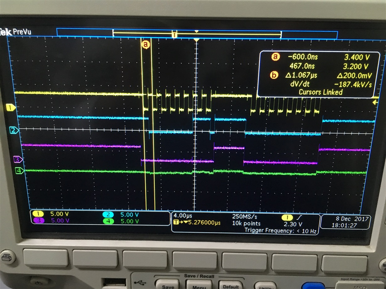
    We have verified on Oscilloscope read address 83h is correctly send to cc1101 module. But Also observe that there is no response in MISO. Clock is set to 1MHz and chip select is low.

    Below are the color coding of signals of attached waveform.
    Yellow: SCLK, Blue: MOSI, Pink: CS, Green: MISO

    Below are the SPI configurations, we have SPI mode 2.

    static uint8_t mode = SPI_CPOL;
    static uint8_t bits = 8;
    static uint32_t speed = 1000000;

    Awaiting for your earliest response.


  • Please check the SPI section in the datasheet (fig 15) . The clock signal should be low in IDLE.
  • Hi,


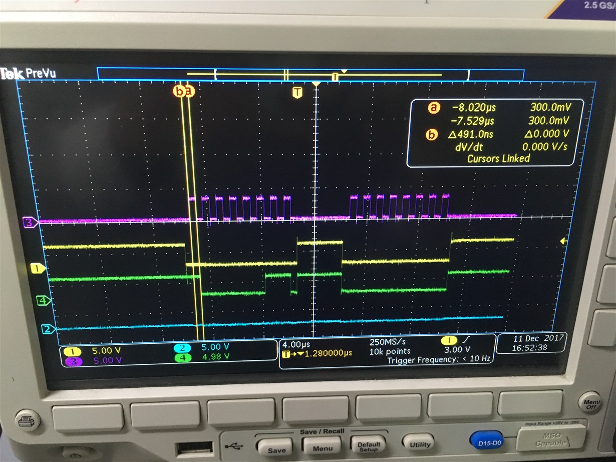
    I have checked with spi mode 1. But there are not getting any output from the slave.

    We are still getting zero from the cc1101 device.

    Below are the color coding of image.

    SCLK - PINK

    CS - YELLOW

    MOSI - GREEN

    MISO - BLUE

  • The SO line is constant low. Normally this should be '1' when CSn goes low and then go low. Is anything connected to the SO line other than than the MCU and the CC1101?
  • Hi,

    There is no any connection with chip SO line except MCU connection.
    We are not using the optional radio control feature as shown in datasheet Table No.24.
    We are trying to read default register value from the cc1101 chip. There is no response from cc1101. Is there any sequence or configuration require before this read operation?

    Awaiting for response.
  • On the CC1101, is:
    RBias = 1.25 V
    DCoupl = 1.8 V

    If you sniff XOSC_Q1, do you see a clock signal?
  • If you are trying to read a register you cannot pull CSn high between the address and the data. Please look at figure 15 in the data sheet or follow the code examples provided by TI.

    BR

    Siri