This thread has been locked.

If you have a related question, please click the "Ask a related question" button in the top right corner. The newly created question will be automatically linked to this question.

LAUNCHXL-CC1310: CSMA/CA

Part Number: LAUNCHXL-CC1310
Other Parts Discussed in Thread: CC1310

Hi, 

Recently we are using CC1310 to develop our own protocol. When implementing slotted CSMA/CA case, sometimes carrier sense says channel is idle but actually some device is transmitting. Could someone please correct me if my comprehension described below is wrong?

Here is my expectation:

Creating a CCA + TX + RX command chain. The absolute starting time of CCA operation is given and TX operation is set to immediate start after CCA detects channel is idle. 

DEV1:      |<== CCA (94*4) tick ==>|<=========TX (30Bytes) ==========>|

DEV2:      |<= Backoff (400 ticks) =>|<== CCA (94*4) tick ==>|    (We should see channel busy here)

Thanks,

Matt


  • Hi

    I recommend that you use the LNA and PA signal and output them on two pins when you debug the issues your are seeing.

    This way you can monitor when the devices are in RX and TX mode, and hence better understand if something is not working the way you expect it to work.

    The signals can be output like this:

    /* Route out LNA active pin to LED1. Asserted when radio is in RX mode */
    PINCC26XX_setMux(ledPinHandle, Board_PIN_LED1, PINCC26XX_MUX_RFC_GPO0);
        
    /* Route out PA active pin to LED2. Asserted when the radio is in TX mode */
    PINCC26XX_setMux(ledPinHandle, Board_PIN_LED2, PINCC26XX_MUX_RFC_GPO1);


    BR

    Siri

  • Thanks siri. 

    After some adjustments, now we can get channel busy when most carrier sense window is covered by TX window. To improve CSMA/CA efficiency, I like to apply carrier sense to the scenario described below:

    CS:   |==Rssi_Sample0 (89us) ==|==Rssi_Sample1 (10us)==|==Rssi_Sample2(10us)==|==Rssi_Sample3(10us)==|    

    TX:   |=====================IDLE=================================|=============TX Frame ======================|

    CS Parameter:

    RF_cmdPropCca.rssiThr =  -70;
    RF_cmdPropCca.csEndTime = 1000; 
    RF_cmdPropCca.startTrigger.triggerType = TRIG_ABSTIME;   
    RF_cmdPropCca.startTime = start_time;

    RF_cmdPropCca.startTrigger.pastTrig = 0;

    RF_cmdPropCca.numRssiBusy = 1; // Number of consecutive RSSI measurements -1 above the threshold

    RF_cmdPropCca.numRssiIdle = 1; // Number of consecutive RSSI measurements -1 above the threshold
    RF_cmdPropCca.csConf.busyOp = 0x1; // End carrier sense on channel Busy
    RF_cmdPropCca.csConf.idleOp = 0x0;

    RF_cmdPropCca.csEndTrigger.triggerType = TRIG_REL_START;

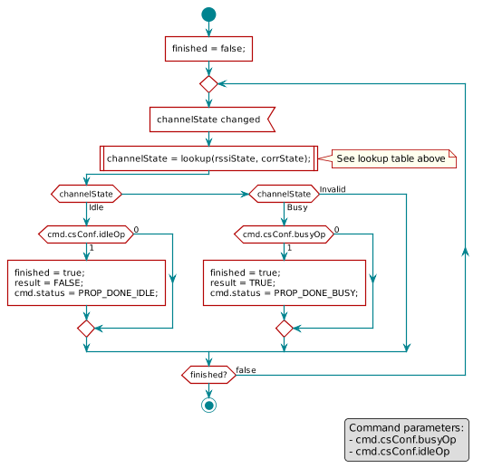
    According to the user guide from docs/proprietary-rf/html/rf-commands-reference/cmd_prop_cs.html,  I should be able to get channel busy if the last Rssi_Sample overlaps with TX window. But the truth is I can only get channel busy when at least 500 RAT ticks of CS window overlap with TX window. This is a bit beyond my comprehension from the RF command reference.   

    Why can't I see the result as the figure described in the RF command reference?

  • Please take a look at:

    https://e2e.ti.com/support/wireless_connectivity/proprietary_sub_1_ghz_simpliciti/f/156/t/662239

    The CS response time described there will give you the time you need in RX to determine that the channel is IDLE. That means that if you have a Sniff mode application, and you set numRssiBusy = 1, it will take around 111 us in RX to determine that there are no signal on the air and go back to SLEEP.

    In the case you are looking at, there is a signal on the air, and hence adjusting the AGC will need to be taken into account. I guess that is what you are seeing when looking at the increased time after turning on the jammer, before the CMD_PROP_CS terminates.

    Siri

  • According to the descriptions from RF user guide, the channel status should be reported every 10 us. That means we should be able to say the channel is busy (with appropriate CS settings) if any of RSSI sample value is higher than the given threshold. Even adjusting AGC will increase the first encountered RSSI sample period up to 4 times, shouldn't I get the result of RSSI_Sampe2 and RSSI_Sampe3 within 60us? 

    CS:   |==Rssi_Sample0 (89us) ==|==Rssi_Sample1 (10us)==|==Rssi_Sample2(10us)==|==Rssi_Sample3(10us)==|    

    TX:   |=====================IDLE=================================|=============TX Frame ======================|


    RX bandwidthValue for rxBwFirst RSSI sampleRSSI sample period
    [kHz]CC13xxCC26xxRssi_0 [µs]Rssi_n[µs]
    1410/1740/2120 47/48/49 13/14/15 89 10

    Matt

  • I talked to our modem designers and they said that the estimation of the ccEnd Time is pretty accurate in the cases where there are not signal on the air. That means that you can use them to estimate current consumption in for example a Sniff mode application, as you will know how long the radio will stay in RX when sniffing (no carrier on the air).
    When measuring on the PA and LNA signals, the timing will not be as accurate as both signals are asserted a bit before the chip enters RX/TX and de-asserted a bit after RX/TX is terminated.
    I did some tests whit settings where RSSI0 should be 98 us and RSSIn is 10 us.
    I set up the CS command such that you should stay in RX and monitor the channel for 10 ms if the channel was available, but terminate as soon as possible if the channel was busy.
    When monitoring the LNA signal on the unit running the CS command and the PA signal on the jammer, I see that RX is terminated around 80 us after the jammer is turned on.
    Only one RSSI sample should be necessary to determine that the channel is busy and this takes 10 us (no AGS adjustments) and up to 40 us with adjustments. There is a big chance that the jammers was turned on in the middle of a sample and that the first sample resulted in reporting IDLE, even if a jammer was present in part of the sample period. Measuring 80 us is then within what to expect.
    Can I ask why it is important for you to find the exact time of cancellation of the command?
    Siri
  • Thanks siri
    To answer your question, we are designing an ultra low power protocol for IoT application that can deal with thousands of devices in a network. If we can improve CS efficiency, that means battery in our device can last longer and also the bandwidth utilization will be better.

    Now go back to CS part, could you share your command settings? I like to see if I can get the same result here :)

    Matt
  • Ok. I Understand. However, there are nothing you can change to decrease this time other than settings numRssiIdle and numRssiBust to its minimum value. The only "problem" I see here is that it can be difficult to calculate the exact time, as we have no formula for calculating the worst case AGC settling time.

    My settings and code is shown below (modifications to the rfListenBeforeTalk example).

    // TI-RTOS RF Mode Object
    RF_Mode RF_prop =
    {
        .rfMode = RF_MODE_PROPRIETARY_SUB_1,
        .cpePatchFxn = &rf_patch_cpe_genfsk,
        .mcePatchFxn = 0,
        .rfePatchFxn = &rf_patch_rfe_genfsk,
    };
    
    // Overrides for CMD_PROP_RADIO_DIV_SETUP
    static uint32_t pOverrides[] =
    {
        // override_use_patch_prop_genfsk.xml
        // PHY: Use MCE ROM bank 4, RFE RAM patch
        MCE_RFE_OVERRIDE(0,4,0,1,0,0),
        // override_synth_prop_863_930_div5.xml
        // Synth: Set recommended RTRIM to 7
        HW_REG_OVERRIDE(0x4038,0x0037),
        // Synth: Set Fref to 4 MHz
        (uint32_t)0x000684A3,
        // Synth: Configure fine calibration setting
        HW_REG_OVERRIDE(0x4020,0x7F00),
        // Synth: Configure fine calibration setting
        HW_REG_OVERRIDE(0x4064,0x0040),
        // Synth: Configure fine calibration setting
        (uint32_t)0xB1070503,
        // Synth: Configure fine calibration setting
        (uint32_t)0x05330523,
        // Synth: Set loop bandwidth after lock to 20 kHz
        (uint32_t)0x0A480583,
        // Synth: Set loop bandwidth after lock to 20 kHz
        (uint32_t)0x7AB80603,
        // Synth: Configure VCO LDO (in ADI1, set VCOLDOCFG=0x9F to use voltage input reference)
        ADI_REG_OVERRIDE(1,4,0x9F),
        // Synth: Configure synth LDO (in ADI1, set SLDOCTL0.COMP_CAP=1)
        ADI_HALFREG_OVERRIDE(1,7,0x4,0x4),
        // Synth: Use 24 MHz XOSC as synth clock, enable extra PLL filtering
        (uint32_t)0x02010403,
        // Synth: Configure extra PLL filtering
        (uint32_t)0x00108463,
        // Synth: Increase synth programming timeout (0x04B0 RAT ticks = 300 us)
        (uint32_t)0x04B00243,
        // override_synth_disable_bias_div5.xml
        // Synth: Set divider bias to disabled
        HW32_ARRAY_OVERRIDE(0x405C,1),
        // Synth: Set divider bias to disabled (specific for loDivider=5)
        (uint32_t)0x18000200,
        // override_phy_rx_aaf_bw_0x0.xml
        // Rx: Set anti-aliasing filter bandwidth to 0x0 (in ADI0, set IFAMPCTL3[7:4]=0x0)
        ADI_HALFREG_OVERRIDE(0,61,0xF,0x0),
        // override_phy_gfsk_rx.xml
        // Rx: Set LNA bias current trim offset to 3
        (uint32_t)0x00038883,
        // Rx: Freeze RSSI on sync found event
        HW_REG_OVERRIDE(0x6084,0x35F1),
        // override_phy_gfsk_pa_ramp_5us_agc_reflevel_0x1e.xml
        // Tx: Configure PA ramping setting (0x10) for approximately 5 us PA ramp time. Rx: Set AGC reference level to 0x1E.
        HW_REG_OVERRIDE(0x6088,0x101E),
        // Tx: Configure PA ramping setting (0x08) for approximately 5 us PA ramp time
        HW_REG_OVERRIDE(0x608C,0x0813),
        // override_phy_rx_rssi_offset_5db.xml
        // Rx: Set RSSI offset to adjust reported RSSI by +5 dB
        (uint32_t)0x00FB88A3,
        // TX power override
        // Tx: Set PA trim to max (in ADI0, set PACTL0=0xF8)
        ADI_REG_OVERRIDE(0,12,0xF8),
        (uint32_t)0xFFFFFFFF,
    };
    
    
    // CMD_PROP_RADIO_DIV_SETUP
    // Proprietary Mode Radio Setup Command for All Frequency Bands
    rfc_CMD_PROP_RADIO_DIV_SETUP_t RF_cmdPropRadioDivSetup =
    {
        .commandNo = 0x3807,
        .status = 0x0000,
        .pNextOp = 0, // INSERT APPLICABLE POINTER: (uint8_t*)&xxx
        .startTime = 0x00000000,
        .startTrigger.triggerType = 0x0,
        .startTrigger.bEnaCmd = 0x0,
        .startTrigger.triggerNo = 0x0,
        .startTrigger.pastTrig = 0x0,
        .condition.rule = 0x1,
        .condition.nSkip = 0x0,
        .modulation.modType = 0x1,
        .modulation.deviation = 0x230,
        .symbolRate.preScale = 0xF,
        .symbolRate.rateWord = 0x40000,
        .rxBw = 0x2C,
        .preamConf.nPreamBytes = 0x4,
        .preamConf.preamMode = 0x0,
        .formatConf.nSwBits = 0x20,
        .formatConf.bBitReversal = 0x0,
        .formatConf.bMsbFirst = 0x1,
        .formatConf.fecMode = 0x0,
        .formatConf.whitenMode = 0x0,
        .config.frontEndMode = 0x0,
        .config.biasMode = 0x1,
        .config.analogCfgMode = 0x0,
        .config.bNoFsPowerUp = 0x0,
        .txPower = 0xAB3F,
        .pRegOverride = pOverrides,
        .centerFreq = 0x0364,
        .intFreq = 0x8000,
        .loDivider = 0x05,
    };
    
    // CMD_FS
    // Frequency Synthesizer Programming Command
    rfc_CMD_FS_t RF_cmdFs =
    {
        .commandNo = 0x0803,
        .status = 0x0000,
        .pNextOp = 0, // INSERT APPLICABLE POINTER: (uint8_t*)&xxx
        .startTime = 0x00000000,
        .startTrigger.triggerType = 0x0,
        .startTrigger.bEnaCmd = 0x0,
        .startTrigger.triggerNo = 0x0,
        .startTrigger.pastTrig = 0x0,
        .condition.rule = 0x1,
        .condition.nSkip = 0x0,
        .frequency = 0x0364,
        .fractFreq = 0x0000,
        .synthConf.bTxMode = 0x0,
        .synthConf.refFreq = 0x0,
        .__dummy0 = 0x00,
        .__dummy1 = 0x00,
        .__dummy2 = 0x00,
        .__dummy3 = 0x0000,
    };
    
    // CMD_PROP_TX
    // Proprietary Mode Transmit Command
    rfc_CMD_PROP_TX_t RF_cmdPropTx =
    {
        .commandNo = 0x3801,
        .status = 0x0000,
        .pNextOp = 0, // INSERT APPLICABLE POINTER: (uint8_t*)&xxx
        .startTime = 0x00000000,
        .startTrigger.triggerType = 0x0,
        .startTrigger.bEnaCmd = 0x0,
        .startTrigger.triggerNo = 0x0,
        .startTrigger.pastTrig = 0x0,
        .condition.rule = 0x1,
        .condition.nSkip = 0x0,
        .pktConf.bFsOff = 0x0,
        .pktConf.bUseCrc = 0x1,
        .pktConf.bVarLen = 0x1,
        .pktLen = 0x1E, // SET APPLICATION PAYLOAD LENGTH
        .syncWord = 0x930B51DE,
        .pPkt = 0, // INSERT APPLICABLE POINTER: (uint8_t*)&xxx
    };
    
    // CMD_PROP_RX
    // Proprietary Mode Receive Command
    rfc_CMD_PROP_RX_t RF_cmdPropRx =
    {
        .commandNo = 0x3802,
        .status = 0x0000,
        .pNextOp = 0, // INSERT APPLICABLE POINTER: (uint8_t*)&xxx
        .startTime = 0x00000000,
        .startTrigger.triggerType = 0x0,
        .startTrigger.bEnaCmd = 0x0,
        .startTrigger.triggerNo = 0x0,
        .startTrigger.pastTrig = 0x0,
        .condition.rule = 0x1,
        .condition.nSkip = 0x0,
        .pktConf.bFsOff = 0x0,
        .pktConf.bRepeatOk = 0x0,
        .pktConf.bRepeatNok = 0x0,
        .pktConf.bUseCrc = 0x1,
        .pktConf.bVarLen = 0x1,
        .pktConf.bChkAddress = 0x0,
        .pktConf.endType = 0x0,
        .pktConf.filterOp = 0x0,
        .rxConf.bAutoFlushIgnored = 0x0,
        .rxConf.bAutoFlushCrcErr = 0x0,
        .rxConf.bIncludeHdr = 0x1,
        .rxConf.bIncludeCrc = 0x0,
        .rxConf.bAppendRssi = 0x0,
        .rxConf.bAppendTimestamp = 0x0,
        .rxConf.bAppendStatus = 0x1,
        .syncWord = 0x930B51DE,
        .maxPktLen = 0xFF, // MAKE SURE DATA ENTRY IS LARGE ENOUGH
        .address0 = 0xAA,
        .address1 = 0xBB,
        .endTrigger.triggerType = 0x1,
        .endTrigger.bEnaCmd = 0x0,
        .endTrigger.triggerNo = 0x0,
        .endTrigger.pastTrig = 0x0,
        .endTime = 0x00000000,
        .pQueue = 0, // INSERT APPLICABLE POINTER: (dataQueue_t*)&xxx
        .pOutput = 0, // INSERT APPLICABLE POINTER: (uint8_t*)&xxx
    };
    
    // CMD_PROP_CS
    rfc_CMD_PROP_CS_t RF_cmdPropCs =
    {
        .commandNo                = CMD_PROP_CS,
        .status                   = 0x0000,
        .pNextOp                  = 0, // Set this to (uint8_t*)&RF_cmdCountBranch in the application
        .startTime                = 0x00000000,
        .startTrigger.triggerType = TRIG_NOW,
        .startTrigger.bEnaCmd     = 0x0,
        .startTrigger.triggerNo   = 0x0,
        .startTrigger.pastTrig    = 0x0,
        .condition.rule           = COND_SKIP_ON_FALSE, // Run next command if this command returned TRUE,
                                                        // skip a number of commands (.condition.nSkip - 1) if it returned FALSE
                                                        // End causes for the CMD_PROP_CS command:
                                                        // Observed channel state Busy with csConf.busyOp = 1:                            PROP_DONE_BUSY        TRUE
                                                        // 0bserved channel state Idle with csConf.idleOp = 1:                            PROP_DONE_IDLE        FALSE
                                                        // Timeout trigger observed with channel state Busy:                              PROP_DONE_BUSY        TRUE
                                                        // Timeout trigger observed with channel state Idle:                              PROP_DONE_IDLE        FALSE
                                                        // Timeout trigger observed with channel state Invalid and csConf.timeoutRes = 0: PROP_DONE_BUSYTIMEOUT TRUE
                                                        // Timeout trigger observed with channel state Invalid and csConf.timeoutRes = 1: PROP_DONE_IDLETIMEOUT FALSE
                                                        // Received CMD_STOP after command started:                                       PROP_DONE_STOPPED     FALSE
        .condition.nSkip          = 0x2, // Number of skips + 1 if the rule involves skipping. 0: Same, 1: Next, 2: Skip next
        .csFsConf.bFsOffIdle      = 0x0, // Keep synthesizer running if command ends with channel Idle
        .csFsConf.bFsOffBusy      = 0x0, // Keep synthesizer running if command ends with Busy
        .__dummy0                 = 0x00,
        .csConf.bEnaRssi          = 0x1, // Enable RSSI as a criterion
        .csConf.bEnaCorr          = 0x0, // Disable correlation (PQT) as a criterion
        .csConf.operation         = 0x0, // Busy if either RSSI or correlation indicates Busy
        .csConf.busyOp            = 0x1, // End carrier sense on channel Busy
        .csConf.idleOp            = 0x0, // Continue on channel Idle
        .csConf.timeoutRes        = 0x0, // Timeout with channel state Invalid treated as Busy
        .rssiThr                  = 0x0, // Set the RSSI threshold in the application
        .numRssiIdle              = 0x0, // Number of consecutive RSSI measurements - 1 below the threshold
                                         // needed before the channel is declared Idle
        .numRssiBusy              = 0x0, // Number of consecutive RSSI measurements -1 above the threshold
                                         // needed before the channel is declared Busy
        .corrPeriod               = 0x0000, // N/A since .csConf.bEnaCorr = 0
        .corrConfig.numCorrInv    = 0x0, // N/A since .csConf.bEnaCorr = 0
        .corrConfig.numCorrBusy   = 0x0, // N/A since .csConf.bEnaCorr = 0
        .csEndTrigger.triggerType = TRIG_REL_START, // Trigs at a time relative to the command started
        .csEndTrigger.bEnaCmd     = 0x0,
        .csEndTrigger.triggerNo   = 0x0,
        .csEndTrigger.pastTrig    = 0x0,
        .csEndTime                = 0x00000000, // Set the CS end time in the application
    };
    
    /* Pin driver handle */
    static PIN_Handle ledPinHandle;
    static PIN_State ledPinState;
    
    /* Application LED pin configuration table: */
    PIN_Config ledPinTable[] =
    {
        Board_PIN_LED1 | PIN_GPIO_OUTPUT_EN | PIN_GPIO_LOW | PIN_PUSHPULL | PIN_DRVSTR_MAX,
        Board_PIN_LED2 | PIN_GPIO_OUTPUT_EN | PIN_GPIO_LOW | PIN_PUSHPULL | PIN_DRVSTR_MAX,
        PIN_TERMINATE
    };
    
    /***** Defines *****/
    #define PAYLOAD_LENGTH          30
    #define PACKET_INTERVAL_US      20000
    /* Number of times the CS command should run when the channel is BUSY */
    #define CS_RETRIES_WHEN_BUSY    2
    /* The channel is reported BUSY if the RSSI is above this threshold */
    #define RSSI_THRESHOLD_DBM      -80
    #define IDLE_TIME_US            5000
    /* Proprietary Radio Operation Status Codes Number: Operation ended normally */
    #define PROP_DONE_OK            0x3400
    
    /***** Prototypes *****/
    static void callback(RF_Handle h, RF_CmdHandle ch, RF_EventMask e);
    
    /***** Variable declarations *****/
    static RF_Object rfObject;
    static RF_Handle rfHandle;
    
    static uint8_t packet[PAYLOAD_LENGTH];
    static uint16_t seqNumber;
    
    static uint32_t time;
    
    /*
     *  ======== txTaskFunction ========
     */
    void *mainThread(void *arg0)
    {
        RF_Params rfParams;
        RF_Params_init(&rfParams);
    
        /* Open LED pins */
        ledPinHandle = PIN_open(&ledPinState, ledPinTable);
        if (ledPinHandle == NULL)
        {
            while(1);
        }
        
        /* Route out LNA active pin to LED1. Asserted when radio is in RX mode */
        PINCC26XX_setMux(ledPinHandle, Board_PIN_LED1, PINCC26XX_MUX_RFC_GPO0);
        
        /* Route out PA active pin to LED2. Asserted when the radio is in TX mode */
        PINCC26XX_setMux(ledPinHandle, Board_PIN_LED2, PINCC26XX_MUX_RFC_GPO1);
    
        /* Customize the CMD_PROP_TX command for this application */
        RF_cmdPropTx.pktLen = PAYLOAD_LENGTH;
        RF_cmdPropTx.pPkt = packet;
        RF_cmdNop.startTrigger.triggerType = TRIG_ABSTIME;
        RF_cmdNop.startTrigger.pastTrig = 1;
        
        RF_cmdNop.pNextOp = (rfc_radioOp_t*)&RF_cmdPropCs;
        RF_cmdPropCs.pNextOp = (rfc_radioOp_t*)&RF_cmdPropTx;
    
        /* Customize the API commands with application specific defines */
        RF_cmdPropCs.rssiThr = RSSI_THRESHOLD_DBM;
        RF_cmdPropCs.csEndTime = 10000;
        
        RF_cmdPropCs.condition.rule = COND_STOP_ON_TRUE;
    
        /* Request access to the radio */
        rfHandle = RF_open(&rfObject, &RF_prop, (RF_RadioSetup*)&RF_cmdPropRadioDivSetup, &rfParams);
    
        /* Set the frequency */
        RF_postCmd(rfHandle, (RF_Op*)&RF_cmdFs, RF_PriorityNormal, NULL, 0);
    
        /* Get current time */
        time = RF_getCurrentTime();
    
        /* Run forever */
        while(true)
        {
            /* Create packet with incrementing sequence number & random payload */
            packet[0] = (uint8_t)(seqNumber >> 8);
            packet[1] = (uint8_t)(seqNumber);
            uint8_t i;
            for (i = 2; i < PAYLOAD_LENGTH; i++)
            {
                packet[i] = rand();
            }
    
            /* Set absolute TX time to utilize automatic power management */
            time += (PACKET_INTERVAL_US * 4);
            RF_cmdNop.startTime = time;
    
            /* Send packet */
            RF_runCmd(rfHandle, (RF_Op*)&RF_cmdNop, RF_PriorityNormal, &callback, 0);
    
            RF_cmdNop.status = IDLE;
            RF_cmdPropCs.status = IDLE;
            RF_cmdPropTx.status = IDLE;
        }
    }
    
    /*
     *  ======== callback ========
     */
    void callback(RF_Handle h, RF_CmdHandle ch, RF_EventMask e)
    {
        if ((e & RF_EventLastCmdDone) && (RF_cmdPropTx.status == PROP_DONE_OK))
        {
            seqNumber++;
        }
    }

    Siri

  • Thanks siri.

    I will try your settings here. Regarding the "uncertain" AGC settling time, do you mean it might make RSSI sample period longer than 40us (comparing to 10us)?

    Matt   

  • I simply meant that we do not have a way to calculate this time exactly. We do not know if the settling takes 4 times or less, and we do not know if it is only one sample period that is affected or more. This will depend on how strong the input signal is and where in the receivers sample period it is first applied.
    Siri