This thread has been locked.

If you have a related question, please click the "Ask a related question" button in the top right corner. The newly created question will be automatically linked to this question.

CCS/cc430f5137: I want example code about dac6311 using.

Part Number: CC430F5137
Other Parts Discussed in Thread: DAC6311, DAC161S997,

Tool/software: Code Composer Studio

Hi,

For using 0-10v output, I try to using dac6311 by I2C interface.

I found datasheet about dac6311.

But, I don't understand this.

Could you provide example code for dac6311 usage?

Please advice for me.

  • HDD,

    We the group that works on the CC430xx devices do not have drivers for that device. I suggest that you repost your question, but this time tag the DAC6311 as the device you care about. Then the E2E system will forward it to that specific DAC group and maybe they can help.

    Sorry,

    Regards,
    /TA
  • Please forward this topic.

    And, I confused DAC6311 using by SPI. So, I want change topic.

    Could you provide example code for dac6311 usage by SPI?
  • Please start a new post yourself with your request and we will close this one.
    BR
    Siri
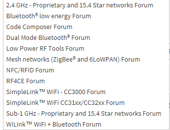
  • In this case, Which forum I select?

    I can select below in your system.

    pls advice.

  • I think you should use this one:
    e2e.ti.com/.../73
    BR
    Siri
  • I have sent an email to someone from the DAC group, I hope he will response soon.

    Regards,
    /TA
  • Hello,

    Yes - as you have correctly identified the DAC6311 interface is indeed SPI and not I2C.

    Generally speaking in DAC we have chosen not to provide device-specific sample code because:

    • Our interfaces implement straight-forward SPI, I2C, or UART interfaces which are readily compatible with MCUs / DSPs
      • This is especially true for DAC6311 - this is just 16-bit frames, you may use either CPOL = 0 or 1, the falling edge is the critical edge
    • Sample code is platform-specific (i.e. sample code for MSP430 does little for you on C2000) and our customer’s platforms vary tremendously

    Where I do actually see value is providing content that is helpful across platforms, like a header file that contains bit-field definitions that makes writing code a bit easier since it’s in a human readable format. Basically it would look something like what's below as an example from the DAC161S997 (please pardon the nasty formatting into the E2E).

    /*********** ADDRESS DEFINITIONS ***********/

    #define       XFER_REG             0x0001

    #define       NOP                  0x0002

    #define       WR_MODE              0x0003

    #define       DACCODE              0x0004

    #define       ERR_CONFIG           0x0005

    /******** REGISTER VALUE DEFINITIONS ********/

    #define       DIS_RETRY_LOOP       0x0080

    #define       EN_RETRY_LOOP        0x0000

    #define       MASK_SPI_ERR         0x0020

    #define       UNMASK_SPI_ERR       0x0000

    This allows the customer to just implement things a bit more directly, in pseudo-code:

    Generic Function:
    spi_write(address, value);

    Function Call:
    spi_write(DACCODE, 0xFFFF);                            // Simple example write to DAC data register
    spi_write(ERR_CONFIG, DIS_RETRY_LOOP || MASK_SPI_ERR); // Slightly more involved write to a register with bitfields

    This is an initiative my Team will support in new developments, but such a thing does not yet exist for DAC6311. It would be extremely easy to provide a simple header since the device doesn't even have registers and instead is simply bit-fields in the 16-bit input frame.

    Please let me know if this is something that would be of interest. Otherwise, generic 16-bit SPI sample code could be used as a basis to communicating with the DAC6311.

  • Hi,

    I have some issue SPI communication to DAC6311.

    I try to execute below code. but MCU doesn't work "P1.4/ PM_UCB0CLK".

    Please advice about below code.

    ////////////////////////////////////////////////////////////////
    // spi function
    ////////////////////////////////////////////////////////////////
    #define SPI_PORT_SEL P1SEL
    #define SPI_PORT_OUT P1OUT
    #define SPI_PORT_REN P1REN
    #define SPI_PORT_DIR P1DIR


    #define DIN_PIN BIT3 // UCB0SIMO pin
    #define SCL_PIN BIT4 // UCB0CLK pin
    #define SYNC_PIN BIT2 // CS pin

    int PtrTransmit;
    unsigned char SPIBufferArray[66];
    unsigned char I2CBuffer;

    void SPIInit()
    {
    SPI_PORT_OUT = SYNC_PIN; // SYNC High
    SPI_PORT_DIR |= SYNC_PIN + SCL_PIN; // Set as Outputs
    SPI_PORT_SEL |= DIN_PIN + SCL_PIN; // Assign SPI pins to USCI_B0

    // Recommended initialisation steps of I2C module as shown in User Guide:
    UCB0CTL1 |= UCSWRST; // Enable SW reset
    UCB0CTL0 |= UCCKPH + UCMSB + UCMST + UCSYNC; // 3-pin, 8-bit SPI master
    UCB0CTL1 |= UCSSEL__SMCLK;
    UCB0BR0 |= 0x02; // /2
    UCB0BR1 = 0; //
    UCB0CTL1 &= ~UCSWRST; // Clear SW reset, resume operation

    }

    void SPIWriteInit()
    {
    UCB0CTL1 |= UCTR; // UCTR=1 => Transmit Mode (R/W bit = 0)
    UCB0IFG &= ~UCTXIFG;
    UCB0IE |= UCTXIE; // enable Transmit ready interrupt

    __bis_SR_register(LPM0_bits + GIE); // Enter LPM0 w/ interrupts
    }

    void SPI_Write(int DataVlaue)
    {
    int SPIData = 0;

    if(DataVlaue > 1023 || DataVlaue < 0)
    {
    return;
    }

    SPIData = (DataVlaue << 4) & 0x03FF; // 10 bit mask (max = 1023)

    SPI_PORT_OUT &= (~SYNC_PIN);

    while(UCB0STAT & UCBUSY); // Waits for completion for shift register and buffer to be empty

    SPIBufferArray[1] = (DataVlaue & 0xFF00) >> 8; // 1 Byte register address
    SPIBufferArray[0] = DataVlaue & 0x00FF;
    PtrTransmit = 1; // set I2CBufferArray Pointer

    SPIWriteInit();

    while(UCB0STAT & UCBUSY); // Waits for completion for shift register and buffer to be empty

    SPI_PORT_OUT |= (SYNC_PIN);

    }
    //-------------------------------------------------------------------------------
    // The USCI_B0 data ISR is used to move received data from the I2C slave
    // to the MSP430 memory. It is structured such that it can be used to receive
    //-------------------------------------------------------------------------------
    #pragma vector = USCI_B0_VECTOR
    __interrupt void USCI_B0_ISR(void)
    {
    if(UCB0IFG & UCTXIFG)
    {
    UCB0TXBUF = SPIBufferArray[PtrTransmit];// Load TX buffer
    PtrTransmit--; // Decrement TX byte counter
    if(PtrTransmit < 0)
    {
    while(!(UCB0IFG & UCTXIFG));
    UCB0IE &= ~UCTXIE; // disable interrupts.
    UCB0IFG &= ~UCTXIFG; // Clear USCI_B0 TX int flag
    __bic_SR_register_on_exit(LPM0_bits); // Exit LPM0
    }
    }
    else if(UCB0IFG & UCRXIFG)
    {
    I2CBuffer = UCB0RXBUF; // store received data in buffer
    __bic_SR_register_on_exit(LPM0_bits); // Exit LPM0
    }
    }

  • and, I have more question.

    For DAC6311, I want make clock 50Mhz.

    I tried to find example codes, they don't work.

    could you provide example code for 50Mhz clock of SPI?

  • Hello,

    Configuring the SCLK of the SPI interface is a function of your MCU platform / available clocks. I would suggest that you post your inquiry concerning clock configurations to the appropriate forum for the controller you're using. Based on the thread history that's the CC430F5137 and the folks supporting those products may still be "listening" to this thread. Otherwise I can make the post for you if you'd like.

    From the DACs perspective 50MHz is an acceptable SCLK assuming AVDD of 3.6V up to 5.5V. For lower supply voltages the maximum SCLK frequency is 20MHz.

    Concerning debugging the code which you posted - can you provide oscilloscope captures of the SCLK, SYNC, and DIN signals for the DAC6311 so we can see what is happening on the bus? Any further details that help describe the problem would be helpful...
  • Hi,

    I understand about your answer. 

    I tried to modify UCSCTLx and SPI registers. and than I find 500 nano second in oscilloscope. it is 2Mhz, right?

    Anyway, I resolved communication issue of DAC6311 by another way.

    And I found DAC6311 is working in lower clock.

    Thnaks