This thread has been locked.

If you have a related question, please click the "Ask a related question" button in the top right corner. The newly created question will be automatically linked to this question.

CC1101: CC1101 Glitch Bit

Part Number: CC1101

Hi all,

We have a product based on the CC1101 radio at 433 MHz that we are altering to use with a client installation. We are using an OOK setup. They have noted that, with their receiver, they have approximately 50% packet loss, and have been able to trace the source of their issue to packets ending with a 0 bit. Their demodulation shows what we are calling a 'burp' after the packet. I've attached an image showing this.

Is there a way we can eliminate this behavior from the CC1101?

Thank you,

Don

  • Don,

    In this mode the CC1101 does not know when to stop, so after the burst has been received the signal is dropping quickly and the AGC of the CC1101 will start to react. Then when it has increased the gain fully the device will start decoding noise. I have seen this little "blip" as an artifact of the AGC that is modifying the gain LNA. There is nothing we can do to change this behavior.

    The last bit is also a "no energy", here you will have to make the AGC slower. Decrease the RBW of the CC1101 or slow down the AGC.

    Regards,
    /TA

  • TA,

    Thanks for the response. To clarify, you are saying that the AGC and LNA have an impact on the transmission behavior of the CC1101? I'm not clear as to what you mean by 'no energy', could you please expand on that?

    Thanks,

    Don
  • No,

    I am talking about the receiver side. When the last bit is done, the RX side will see "no signal" and start to increase the gain of the LNA's using the algorithm managed by the AGC "Automatic Gain Controler"

    Regards,
    /TA
  • TA,

    Thanks for the clarification, that is the way I understood those registers to work so the response confused me. The issue is not with the RX function of the CC1101, since we are not in fact receiving with a CC1101. Our client is using a different RF component to rx data that we tx with the CC1101. Is there an explanation for why there is a burst of RF energy transmitted FROM the CC1101?

    Thanks,

    Don

  • I do not think there is, please make a plot using a spectrum analyzer in a zero-span mode and we can use that as a reference.

    Regards,
    /TA
  • TA,

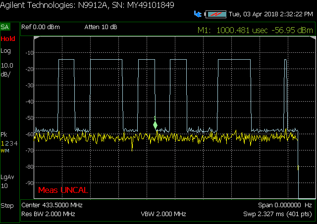
    I've attached a capture from our RF analyzer. Our data rate is ~7.5 kHz. Looking at the width of the pulse at the end of the scan indicates that it is not an intentional bit. This is the pulse that is causing problems for us.

    Thanks,

    Don

  • Do you use PA ramping? Is the data manchester coded? It could be that I have seen something like this before but at the moment I'm not able to remember the details. If PA ramping is used it could be related to the ramping. I can't remember at the moment if CC1101 insert a extra symbol or not to do the ramping at the start/ end of a packet but if an extra bit is used this is a copy of the last bit. Could you check if this spike is related to the last bit you send (if this is '0' or '1'?
  • TER,

    We have noted this behavior only in packets that end with a 0 bit. The full settings we use on startup are copied from the source files below:


    #define IOCFG0_SETTING 0x06 //ATEST will assert when RSSI is below the threshold set in CCA_MODE
    #define FIFOTHR_SETTING 0x47
    #define SYNC1_SETTING 0xFF
    #define SYNC0_SETTING 0xFF
    #define PKTLEN_SETTING 0xFF
    #define PKTCTRL1_SETTING 0x00//dap0x04
    #define PKTCTRL0_SETTING 0x00//dap0x05
    #define ADDR_SETTING 0x00
    #define CHANNR_SETTING 0x00
    #define FSCTRL1_SETTING 0x06
    #define FSCTRL0_SETTING 0x00
    #define FREQ2_SETTING 0x10

    // 433.92
    #define FREQ1_SETTING 0xB0
    #define FREQ0_SETTING 0xE2//433.919830

    #define MDMCFG4_SETTING 0xF8//7.576
    #define MDMCFG3_SETTING 0x32//0x15
    #define MDMCFG2_SETTING 0xB8//0x38//dap0x3B
    #define MDMCFG1_SETTING 0x22
    #define MDMCFG0_SETTING 0xF8
    #define DEVIATN_SETTING 0x15
    #define MCSM2_SETTING 0x07
    #define MCSM1_SETTING 0x30
    #define MCSM0_SETTING 0x18
    #define FOCCFG_SETTING 0x16
    #define BSCFG_SETTING 0x6C
    #define AGCCTRL2_SETTING 0x04//dap0x03
    #define AGCCTRL1_SETTING 0x00//dap0x40
    #define AGCCTRL0_SETTING 0x92//dap0x91
    #define WOREVT1_SETTING 0x87
    #define WOREVT0_SETTING 0x6B
    #define WORCTRL_SETTING 0xFB
    #define FREND1_SETTING 0x56
    #define FREND0_SETTING 0x11
    #define FSCAL3_SETTING 0xE9
    #define FSCAL2_SETTING 0x2A
    #define FSCAL1_SETTING 0x00
    #define FSCAL0_SETTING 0x1F

    #define POWER_9_9               0xC0

    void cc1101_Init()

    {

    cc1101WriteRegister(IOCFG0, IOCFG0_SETTING);
    cc1101WriteRegister(FIFOTHR, FIFOTHR_SETTING);
    cc1101WriteRegister(SYNC1, SYNC1_SETTING);
    cc1101WriteRegister(SYNC0, SYNC0_SETTING);
    cc1101WriteRegister(PKTLEN, PKTLEN_SETTING);
    cc1101WriteRegister(PKTCTRL1, PKTCTRL1_SETTING);
    cc1101WriteRegister(PKTCTRL0, PKTCTRL0_SETTING);
    cc1101WriteRegister(ADDR, ADDR_SETTING);
    cc1101WriteRegister(CHANNR, CHANNR_SETTING);
    cc1101WriteRegister(FSCTRL1, FSCTRL1_SETTING);
    cc1101WriteRegister(FSCTRL0, FSCTRL0_SETTING);
    cc1101WriteRegister(FREQ2, FREQ2_SETTING);
    cc1101WriteRegister(FREQ1, FREQ1_SETTING);
    cc1101WriteRegister(FREQ0, FREQ0_SETTING);
    cc1101WriteRegister(MDMCFG4, MDMCFG4_SETTING);
    cc1101WriteRegister(MDMCFG3, MDMCFG3_SETTING);
    cc1101WriteRegister(MDMCFG2, MDMCFG2_SETTING);
    cc1101WriteRegister(MDMCFG1, MDMCFG1_SETTING);
    cc1101WriteRegister(MDMCFG0, MDMCFG0_SETTING);
    cc1101WriteRegister(DEVIATN, DEVIATN_SETTING);
    cc1101WriteRegister(MCSM2, MCSM2_SETTING);
    cc1101WriteRegister(MCSM1, MCSM1_SETTING);
    cc1101WriteRegister(MCSM0, MCSM0_SETTING);
    cc1101WriteRegister(FOCCFG, FOCCFG_SETTING);
    cc1101WriteRegister(BSCFG, BSCFG_SETTING);
    cc1101WriteRegister(AGCCTRL2, AGCCTRL2_SETTING);
    cc1101WriteRegister(AGCCTRL1, AGCCTRL1_SETTING);
    cc1101WriteRegister(AGCCTRL0, AGCCTRL0_SETTING);
    cc1101WriteRegister(WOREVT1, WOREVT1_SETTING);
    cc1101WriteRegister(WOREVT0, WOREVT0_SETTING);
    cc1101WriteRegister(WORCTRL, WORCTRL_SETTING);
    cc1101WriteRegister(FREND1, FREND1_SETTING);
    cc1101WriteRegister(FREND0, FREND0_SETTING);
    cc1101WriteRegister(FSCAL3, FSCAL3_SETTING);
    cc1101WriteRegister(FSCAL2, FSCAL2_SETTING);
    cc1101WriteRegister(FSCAL1, FSCAL1_SETTING);
    cc1101WriteRegister(FSCAL0, FSCAL0_SETTING);
    cc1101WriteRegister(PATABLE, POWER_9_9);

    }

    Thanks,

    Don

  • Please try to modify

    #define FREND0_SETTING 0x11

    to

    #define FREND0_SETTING 0x10

    And also modify the PA table so that the initial value is 0x50.

    /TA
  • TA,

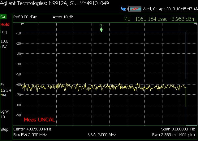
    I've made the recommended changes and it seems to break our link altogether. When a packet is transmitted the zero span now looks like this:

    It seems like the radio is on for both '1' and '0'.

  • Hi Don,

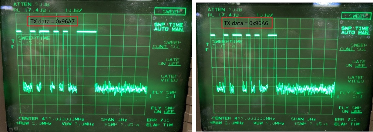
    I don't see the same issue. I have attached the register settings and spectrum plots. Can you try these settings and see what you get?

    The settings are exported from SmartRF studio.

    Regards.

    433MHZ_OOK_CC1101_reg_config.c
    static const registerSetting_t preferredSettings[]= 
    {
      {CC1101_IOCFG2,            0x29},
      {CC1101_IOCFG1,            0x2E},
      {CC1101_IOCFG0,            0x06},
      {CC1101_FIFOTHR,           0x47},
      {CC1101_SYNC1,             0xD3},
      {CC1101_SYNC0,             0x91},
      {CC1101_PKTLEN,            0x02},
      {CC1101_PKTCTRL1,          0x04},
      {CC1101_PKTCTRL0,          0x00},
      {CC1101_ADDR,              0x00},
      {CC1101_CHANNR,            0x00},
      {CC1101_FSCTRL1,           0x06},
      {CC1101_FSCTRL0,           0x00},
      {CC1101_FREQ2,             0x10},
      {CC1101_FREQ1,             0xA7},
      {CC1101_FREQ0,             0x62},
      {CC1101_MDMCFG4,           0xF8},
      {CC1101_MDMCFG3,           0x2E},
      {CC1101_MDMCFG2,           0x30},
      {CC1101_MDMCFG1,           0x02},
      {CC1101_MDMCFG0,           0xF8},
      {CC1101_DEVIATN,           0x15},
      {CC1101_MCSM2,             0x07},
      {CC1101_MCSM1,             0x30},
      {CC1101_MCSM0,             0x18},
      {CC1101_FOCCFG,            0x14},
      {CC1101_BSCFG,             0x6C},
      {CC1101_AGCCTRL2,          0x03},
      {CC1101_AGCCTRL1,          0x40},
      {CC1101_AGCCTRL0,          0x92},
      {CC1101_WOREVT1,           0x87},
      {CC1101_WOREVT0,           0x6B},
      {CC1101_WORCTRL,           0xFB},
      {CC1101_FREND1,            0x56},
      {CC1101_FREND0,            0x11},
      {CC1101_FSCAL3,            0xE9},
      {CC1101_FSCAL2,            0x2A},
      {CC1101_FSCAL1,            0x00},
      {CC1101_FSCAL0,            0x1F},
      {CC1101_RCCTRL1,           0x41},
      {CC1101_RCCTRL0,           0x00},
      {CC1101_FSTEST,            0x59},
      {CC1101_PTEST,             0x7F},
      {CC1101_AGCTEST,           0x3F},
      {CC1101_TEST2,             0x81},
      {CC1101_TEST1,             0x35},
      {CC1101_TEST0,             0x09},
      {CC1101_PARTNUM,           0x00},
      {CC1101_VERSION,           0x04},
      {CC1101_FREQEST,           0x00},
      {CC1101_LQI,               0x01},
      {CC1101_RSSI,              0x80},
      {CC1101_MARCSTATE,         0x01},
      {CC1101_WORTIME1,          0x00},
      {CC1101_WORTIME0,          0x00},
      {CC1101_PKTSTATUS,         0x00},
      {CC1101_VCO_VC_DAC,        0x94},
      {CC1101_TXBYTES,           0x00},
      {CC1101_RXBYTES,           0x00},
      {CC1101_RCCTRL1_STATUS,    0x00},
      {CC1101_RCCTRL0_STATUS,    0x00},
    };

  • FI,

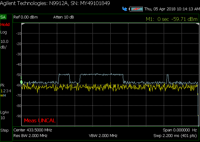
    Thanks for the suggestions. I've implemented the register settings that you posted (with the exception of FREQ2, FREQ1, and FREQ0) and captured the following output:

    You can see that the extra RF output still persists. For the record, the last two bytes we are sending in this packet are 0x29 and 0xB8 (in that order). This packet is 8 bytes long total. Is it possible we are using different HW revisions of the component? The contents of PARTNUM are 0xF0, and the contents of VERSION are 0x0F on my board.

    In my code, in order to TX, I load the FIFO with my packet, adjust PKTLEN to match the number of bytes I intend to send, and then strobe the STX command. After the CC1101 exits the TX state I change the PKTLEN register to 0xFF. Last, since this is a low power application, after PKTLEN is changed I set the IOCFG registers to 0x2F, strobe the SIDLE command, then wait for MARCTATE to indicate the radio is idling, then I strobe the SPWD command.  Would any of this cause the behavior I am seeing?

    Don

  • FI,

    Is there any update on this?

    Don
  • Don,

    Sorry, we are not able to reproduce the glitch on our end. I have asked R&D and they have never heard of such an issue on this device, could it be something in your application.

    Regards,
    /TA