This thread has been locked.

If you have a related question, please click the "Ask a related question" button in the top right corner. The newly created question will be automatically linked to this question.

CC1125: Help with determining settings of a CC1125 radio

Part Number: CC1125

Hello,

I am trying to build a radio receiver to pick up transmissions from a commercial off the shelf (COTS) CC1125 based radio.

I have picked up the traffic between the CC1125 and host microcontroller of the COTS radio, and replicated the settings on a CC1125 evaluation board.

However the data being received by the CC1125 eval board does not match what is being transmitted by the radio.  

I have verified transmissions with another COTS radio of the same kind and that there is no encoding of the data before transmissions by analyzing the traffic between the host micro and CC1125 of the COTS radio. 

Please find the traffic analysis between the micro and the CC1125 of the COTS radio attached. A payload of 0x02700CAABBCCDDEEFF03 is transmitted and received by the COTS radio.

Screenshots of the CC1125 eval software is also shown, which does not match the transmitted data.

Any help is much appreciated.

COTS_transmitter_traffic.docxCOTS_receiver_traffic.docx Thank you,
Arjun

  • Hi,
    Have you tried disabling Whitening?
  • FI said:
    Hi,
    Have you tried disabling Whitening?

    I have tried disabling whitening, but it gives me the a similar result. 

    When I look at the PKT_CFG1 register, it is set for 0x41, indicating the PKT_CFG1.WHITE_DATA = 1.

    So I take that whitening must be enabled on the COTS radio.

    Please see attached the initial register settings of the radio on power up to this post.

    I am also attaching the data dump from the CC1125 evaluation board, with a transmit payload of 0x 02 AA BB CC DD EE FF <4-byte-checksum> 03.

    The checksum is added by the microcontroller, and 02 and 03 are start and stop bytes. Eleven received packets are shown in the attachment.

    Thanks

    COTS_radio_register_setup.xlsxAABBCCDDEEFF_CC1125_receive_data.docx

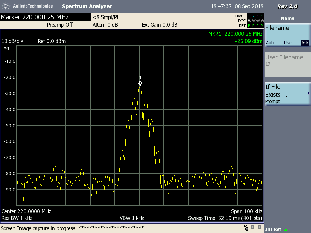
  •  Another thing I noticed was that I had to set the RX bandwidth to a relatively high number > 100 KHz for the CC1125 eval receiver software application to display any data. The transmit bandwidth is supposed to be only 12.5 KHz. Please see COTS radio output spectrum below. Am I missing something here?

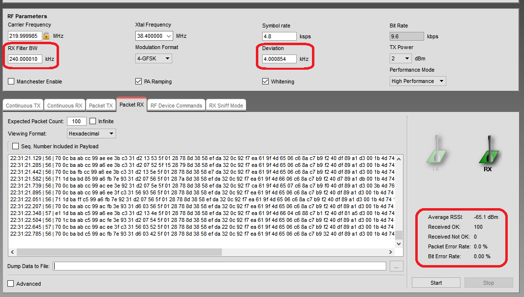
  • Please see a synopsis of the CC1125 eval board captured data using SmartRF studio. The number of bytes received using SmartRF Studio seems to agree with the expected payload size. However the data is not being properly decoded / displayed. Any suggestions? 

    The data transmitted contains a start byte (0x02), stop byte (0x03), a length field (2 bytes) and the data. A checksum (4 bytes) is and RSSI (1 byte) is added to the received payload by the receiver host controller.

    Payload

    Data 2018/05/23 21:51:58.267 - (Tx) 02000512345603

    2018/05/23 21:51:58.329 - (Rx) 0200091234562C7BF9EA03E1

    With Whitening

    21:51:13.081 | 56 | e0 0d 12 74 17 39 6e e8 ea 42 68 25 c2 02 5f 01 28 78 8d 38 58 ef da 32 0c 92 f7 ea 61 9f 4d 65 06 c6 8a c7 b8 b2 40 df 89 a1 d3 00 1b 4d 74 15 91 91 d0 93 cc df 98 82 86 1b 58 67 42 8a d6 ba a5 53 98 a3 9d 8d 47 20 68 8c 59 ed 9e 7e 70 ff eb 43 b9 e3 53 88 | -163

    Without whitening

    21:51:37.769 | a8 | 61 04 80 89 82 1a 1a 12 90 80 45 55 55 55 95 55 55 55 55 55 55 55 55 59 55 55 55 55 55 55 55 5d 55 55 55 55 55 55 75 55 55 55 55 55 55 55 55 55 55 55 55 7d 55 55 57 55 55 55 55 75 55 55 55 55 55 55 55 5d 55 55 54 55 55 55 57 55 55 55 55 55 65 55 55 45 57 55 55 55 55 55 57 55 55 55 5d 55 55 55 55 55 55 55 55 5d 55 55 15 55 55 55 55 55 55 15 55 55 55 55 55 55 55 55 55 55 50 55 55 55 55 55 55 55 55 55 55 55 55 55 55 55 55 55 55 55 55 95 55 55 55 55 55 55 55 55 55 55 55 55 55 55 55 55 55 55 55 55 55 59 | -163

  • Do you know why the RX BW isa set very wide compared to the datarat/ deviation?

    It could be that some assumption about the sent data is incorrect.

    Do you know that variable packet length is used? Would using fixed change something?
    How do you know that you have the correct sync word?
    Try setting fixed packet length and the sync word equal to 0xAAAA and check what you receive given that the sender send a preamble.
    When you write that a start and stop bit is used, how do you know?
  • Thanks for the response.

    The RX BW is the part that I am confused about.
    The frequency setup I read from the device, and confirmed by the output spectrum is for 220 MHz, with a 38.4 MHz crystal.
    Sync word is setup at power up as 0x0B93DE51, based on the register settings. It is a bit strange, since the manufacturer is reversing the byte order of what would otherwise be the default sync word (0x930B51DE).

    0F 0x0F(04 0x04)
    0F 0x0F(0B 0x0B)

    0F 0x0F(05 0x05)
    0F 0x0F(93 0x93)

    0F 0x0F(06 0x06)
    0F 0x0F(DE 0xDE)

    0F 0x0F(07 0x07)
    0F 0x0F(51 0x51)

    Variable packet length is what the radio is setup for, as I can send and receive variable length payloads.
    There is no control of the packet length field, as it is under the control of the host microcontroller.
    The start and stop bytes are added by the host microcontroller, which can be read by analyzing the traffic between the two.

    Are there any other parameters apart from what the below, that I should be configuring?

    Set frequency to 220000012.2 MHz
    0F 0x0F(2F 0x2F) Set freq
    00 0x00(0C 0x0C)
    0F 0x0F(5B 0x5B)

    0F 0x0F(2F 0x2F) Set freq
    00 0x00(0D 0x0D)
    0F 0x0F(AA 0xAA)

    0F 0x0F(2F 0x2F) Set freq
    00 0x00(0E 0x0E)
    0F 0x0F(AB 0xAB)

    Write DEVIATION_M = 0xE0, setup to configure frequency deviation to 2.197 KHz.
    0F 0x0F(0A 0x0A)
    0F 0x0F(E0 0xE0)

    Write MODCFG_DEV_E = 29, Normal mode, 4-GFSK, Deviation exponent = 0x1
    0F 0x0F(0B 0x0B)
    0F 0x0F(29 0x29)

    Write CHAN_BW = 0E, configures channel bandwidth to roughly 17.2 KHz.
    Channel filter enabled, decimation factor = 20.
    0F 0x0F(11 0x11)
    0F 0x0F(0E 0x0E)

    Configures symbol rate to 4.8 ksps. Symbol rate exponent = 6, symbol rate mantissa = 0x624E.
    0F 0x0F(14 0x14) Write SYMBOL_RATE2 = 60
    0F 0x0F(60 0x60)

    0F 0x0F(15 0x15) Write SYMBOL_RATE1 = 62
    0F 0x0F(62 0x62)

    0F 0x0F(16 0x16) Write SYMBOL_RATE0 = 4E
    0F 0x0F(4E 0x4E)

    0F 0x0F(2D 0x2D) Write PA_CFG0 = 7E
    0F 0x0F(7E 0x7E)

    Write AGC_GAIN_ADJUST= 0xA7 = 167. RSSI offset configuration.
    0F 0x0F(19 0x19)
    0F 0x0F(A7 0xA7)

    Write AGC_CS_THR = 0xA6. AGC carrier sense threshold
    0F 0x0F(18 0x18)
    0F 0x0F(A6 0xA6)

    SFRX. Flush RX FIFO.
    0F 0x0F(3A 0x3A)

    Write PKT_CFG0 = 40, Infinite packet length mode, UART mode disabled, start/stop bit swap disabled.
    0F 0x0F(28 0x28)
    0F 0x0F(40 0x40)

    Write FIFO_CFG = 02. CRC_AUTOFLUSH disabled, FIFO threshold = 2, TX_FIFO = 125, RX_FIFO = 3
    0F 0x0F(1E 0x1E)
    0F 0x0F(02 0x02)

    Thank you again.
  • I took a look at COTS_radio_register_setup.xlsx.

    A few details:
    - Most of the sync word registers are written, but it's one that is labeled burst read.
    - I notice that even though the RX BW is max, the IF is set to a value different than 0. Even though the RX BW is set high in the radio you are trying to communicate with, I would set it to something more in line with the datarate/ deviation.
    - Have you tried to use 0xAAAA as sync and see what you actually receive in this case?
  • TER said:
    I took a look at COTS_radio_register_setup.xlsx.

    A few details:
    - Most of the sync word registers are written, but it's one that is labeled burst read.

    This is just way I did the Excel formula. Its looking at the burst bit of every byte. This is actually a single register access, with a data byte that has the a 1 for the bit 6. For example 0xDE at register 06.

     
    - I notice that even though the RX BW is max, the IF is set to a value different than 0. Even though the RX BW is set high in the radio you are trying to communicate with, I would set it to something more in line with the datarate/ deviation.

    Looking at the FREQ_IF_CFG register value of 0x33, I get the receiver mixer frequency to be roughly 59.76 KHz. My understanding is that the radio has a non zero-IF architecture, which is what the CC1125 user guide recommends. Is that calculation correct, and also is that mixer frequency reasonable? I am attaching the IF calculator with this post.The COTS radios register settings for RX BW tells me it should be around 17 KHz, which is in line with the >=2X requirement for CHAN_BW.CHFILT_BYPASS = 0

    However, when I set the RX BW to be a number lower than the mixer frequency, I am not getting any output from the SmartRF studio software.


    - Have you tried to use 0xAAAA as sync and see what you actually receive in this case?

    I have not tried setting the sync word to 0xAAAA, I will do that shortly. Shouldn't it be a 32 bit sync word or 0xAAAAAAAA?

    Thanks

    IF_calc.xlsx

  • I tried using AAAAAAAA as the sync word, and I am getting similar results.
    Please see below.

    Payload with sync word AAAAAAAA

    2018/05/29 20:49:43.599 - (Tx) 020008AABBCCDDEEFF03
    2018/05/29 20:49:43.662 - (Rx) 02000CAABBCCDDEEFF3F8335C703DD


    With Whitening

    20:48:23.979 | 77 | 65 55 37 cd 3e 48 b6 cb 41 5a 39 73 96 71 80 fc dd 3d d8 6d c7 93 8f 72 0c 92 f7 ea 61 ab 4d 65 06 ce 82 c7 b9 f2 40 df 89 91 d3 01 1b e9 fa dd 81 91 80 93 c4 df 98 b2 84 2b 5c 47 42 0a d6 ae a9 6b 98 a3 92 4c 4f 20 68 bc 49 ed bf 7e 53 ff eb 4b ba e3 53 88 a2 e6 f9 35 84 0a 4f 30 49 cd fc 9c 3a 1c bb 86 5f 10 fb 26 96 7d 72 d9 45 75 37 bf 3f b6 1d b0 b3 | -170

    20:48:24.993 | 77 | 69 99 82 55 a5 99 4e 38 5a fc b1 70 95 57 6a de d5 8d 98 6d 0d 30 a7 6f 20 12 77 ea 6e bf ad 65 04 76 8a c7 b9 da 40 f4 81 a1 d3 28 53 dd 74 15 91 91 80 93 c4 df 98 b2 84 1f 5c 57 42 8a d6 aa 25 5b 98 e3 97 4c 47 20 a8 bd 49 ed be 7e 50 ff 2b 43 ba 61 73 80 92 ee 39 1e 34 0a 4f b0 7a c5 cc ac 3a 1e a3 b6 5f 10 3b 2f 96 7f 32 d9 55 79 cf b5 95 be 1d 80 b3 | -170

    20:48:26.021 | 77 | 69 9d d2 54 a4 dd 0e 38 5b fc b1 70 94 57 2a de d5 8d c8 7d 0d 30 a7 67 0c 92 c7 ea a5 9f 4d 65 06 c6 8a c3 b9 f2 24 ef 89 a1 d3 80 9b 5d 74 16 91 91 80 83 c4 df 98 b2 b4 8b 5c 67 42 da d6 aa a5 db 98 e3 97 4c f7 20 6b be 49 ed 9a 7a 52 ff eb 73 b9 e3 53 b8 52 e6 7b 36 84 0a 4f 30 59 cd fc 9c 3a 1c a3 8e 5f 10 3b 2e d6 7f 72 d9 45 79 37 b7 b7 16 3d 90 b3 | -170


    Without Whitening

    20:49:19.186 | 88 | 88 80 08 b8 20 bb 2e d2 20 2e 88 00 03 00 20 8a a8 a0 10 10 00 ca 28 02 5c 9d 55 55 59 5b 55 55 57 59 45 75 57 c7 55 d5 55 75 75 7d 65 75 b5 55 b5 b5 55 d7 e7 35 57 6f 85 5d fd 5d 55 d7 5d 55 d4 f9 56 56 55 77 57 54 7d 55 d5 75 75 1b 55 55 55 65 55 55 53 5c 57 55 55 d5 75 54 1d 55 75 55 75 51 55 5d 49 65 55 55 55 55 15 59 55 55 55 55 55 55 55 71 55 55 55 55 55 57 55 55 55 55 57 1e 55 d5 15 5d 55 53 55 73 | -171

    20:49:20.204 | 88 | 80 48 e8 20 ba 2b 82 20 2e 88 00 1a 81 20 8a a8 a0 40 11 00 8a 29 02 15 51 75 55 65 c5 55 55 56 55 55 54 55 55 55 59 55 55 55 57 f7 55 55 f5 55 55 05 55 15 55 d5 55 55 55 55 55 55 55 55 55 57 55 93 55 55 55 55 53 d5 55 55 55 59 54 55 55 55 55 50 55 77 55 55 55 55 77 55 55 55 55 55 05 55 55 55 55 95 d5 55 55 54 55 75 77 55 5d 55 55 15 45 55 6d 5b 4d 55 5f 7d 55 65 57 55 5d 57 55 55 55 55 55 55 55 55 55 55 | -170

    20:49:21.230 | 88 | 88 44 8a d2 0b a7 a9 22 12 e8 80 00 20 06 08 aa 8a 04 01 00 08 a2 80 25 55 55 65 55 55 56 55 55 55 55 55 55 55 59 55 55 54 55 55 57 55 55 55 55 55 55 75 55 55 5e 55 55 5d 55 55 d7 55 5d 55 55 55 55 55 55 55 55 55 55 55 55 55 55 55 55 55 55 55 b5 55 55 55 5d 55 17 41 55 d5 55 5d 57 55 55 56 56 55 d5 55 55 55 55 55 57 55 55 55 55 75 55 dd 55 f5 57 f8 75 55 55 11 d7 54 45 55 d7 d4 1d 6e 54 65 76 37 5d 5e 57 | -171
  • I haven't had the time to look at this today and I will be out the next few days. Could you look into mapping of the 4 GFSK symbols, can't remember what options we had there (meaning what -1 dev maps to etc.
  • TER said:
    I haven't had the time to look at this today and I will be out the next few days. Could you look into mapping of the 4 GFSK symbols, can't remember what options we had there (meaning what -1 dev maps to etc.
    Frequency modulation is left to its default.

    CFM_DATA_CFG = 0x00
    Symbol Map configuration is 00:-Dev/3, 01:-Dev, 10:Dev/3, 11:Dev
    CFM mode is disabled

    Also 

    MODCFG_DEV_E = 0x2A = b00101010
    Modem Mode = Normal Mode
    Modulation format = 4-GFSK
    Deviation Exponent = 2, This is however changed later to Deviation Exponent = 1, by setting MODCFG_DEV_E = 0x29.

  • Another item I am curious about is the minimum number of preamble bits that are to be transmitted parameter = PREAMBLE_CFG1.NUM_PREAMBLE. How does the receiver determine that the preamble is done and that the sync word has begun?

    It is set to b0111 or 5 bytes at the COTS transmitter. Would this have anything to do with the receiver not being able to determine the sync word or the beginning of the payload properly?
  • A question regarding the RSSI update rate.

    Based on the register settings of the COTS radio, the RSSI update rate must be less than 0.7s.

    This seems like a very large number, and I wonder if the RX is still looking for the preamble and sync, long after it is complete.

    T1_Calc.xlsx

    T2_Calc.xlsx

  • Received data not the same sent data:
    If you use the same settings on the RX and TX side you will receive the same as you send. So the way I see it you either don't use the same settings on the RX and TX side or the content in the TX FIFO is different from what you believe it is. If you have access to a spectrum that are capable of demodulating you would be able to see what is on the air.

    From what I can see you are set the sync word correctly since without it you would not be able to receive anything. This indicate that payload. If the settings for Manchester, whitening and mapping of 4-GFSK symbols are different on the RX and TX side you can see that the data received is different on the RX and TX side.

    In CC1125 preamble is only used to settle the AGC. Only 4 bit is needed (4 byte if zero IF used). The sync search uses a waveform compare meaning it looks for a waveform equal to the programmed one and when a match is found the sync word is found.

    Not sure where you get the RSSI update rate number from?

    The excel sheet found in www.ti.com/.../swra428a.pdf can be used for calculations.

    You wrote:
    Payload with sync word AAAAAAAA

    2018/05/29 20:49:43.599 - (Tx) 020008AABBCCDDEEFF03
    2018/05/29 20:49:43.662 - (Rx) 02000CAABBCCDDEEFF3F8335C703DD

    but the with/ without whitening logg looks like it contains different data. Could you explain the relationship between the data I copied in here and the rest of the data in that post?
  • TER said:
    Received data not the same sent data:
    If you use the same settings on the RX and TX side you will receive the same as you send. So the way I see it you either don't use the same settings on the RX and TX side or the content in the TX FIFO is different from what you believe it is. If you have access to a spectrum that are capable of demodulating you would be able to see what is on the air.

    From what I can see you are set the sync word correctly since without it you would not be able to receive anything. This indicate that payload. If the settings for Manchester, whitening and mapping of 4-GFSK symbols are different on the RX and TX side you can see that the data received is different on the RX and TX side.

    In CC1125 preamble is only used to settle the AGC. Only 4 bit is needed (4 byte if zero IF used). The sync search uses a waveform compare meaning it looks for a waveform equal to the programmed one and when a match is found the sync word is found.

    Not sure where you get the RSSI update rate number from?

    The excel sheet found in www.ti.com/.../swra428a.pdf can be used for calculations.

    You wrote:
    Payload with sync word AAAAAAAA

    2018/05/29 20:49:43.599 - (Tx) 020008AABBCCDDEEFF03
    2018/05/29 20:49:43.662 - (Rx) 02000CAABBCCDDEEFF3F8335C703DD

    but the with/ without whitening logg looks like it contains different data. Could you explain the relationship between the data I copied in here and the rest of the data in that post?

    OK, I will look closely at the traffic between the radio and the controller. Based on my previous analysis of the traffic between the radio controller and the CC1125, I can see that Manchester encoding is disabled, whitening is enabled and that the modulation is 4-GFSK.

    The timing calculations are from the equations provided in SWRU295, CC112x User's Guide, pages 39-41. I plugged the reg settings I see from the radio and it throws an error. I have narrowed the cause of error to a single register, the AGC_CFG0. The value I read from the COTS radio is 0x5F, which results in the RSSI_VALID_CNT = 9. This causes an error with the calculator. Any other value of the RSSI_VALID_CNT is acceptable. I am attaching the spreadsheet with the calculations in this post. If I manually set AGC_CFG0.RSSI_VALID_CNT = 9 in the CS Response Time tab, I do get the 0.7s number for Max CS Response Time. So now I think there is something wrong with the way the AGC configurations are set in the COTS radio, or the sniffer might be reading it wrong. Would you be able to shed some light on this?

    The with and without whitening logs are data dumps from the SmartRF tool. It is the data captured by a CC1125 evaluation board, when receiveing packets from the COTS radio. The COTS radio TX and RX is what I have below.

    2018/05/29 20:49:43.599 - (Tx) 020008AABBCCDDEEFF03
    2018/05/29 20:49:43.662 - (Rx) 02000CAABBCCDDEEFF3F8335C703DD

    I can see the data being fed into the transmitter as is, without any encoding. Please see the traffic below. I will go through the register settings to ensure there is no Manchester encoding. Even if it is Manchester coded, is it just a matter of enabling it in the receiver to see the correct data?

    SFTX. Flush the TX FIFO. 

    0F 0x0F(3B 0x3B)

    Write FIFO_CFG = 0x 7B. FIFO_THR = 123. Bytes in TX FIFO = 4, Bytes in RX FIFO = 124.

    0F 0x0F(1E 0x1E)
    0F 0x0F(7B 0x7B)


    Write PKT_CFG0 = 0x00. Fixed packet length mode, UART mode disabled, start/stop bit swap disabled.
    0F 0x0F(28 0x28)
    0F 0x0F(00 0x00)


    Write PKT_LEN = 0x0E = 15. Packet length = 15 bytes.
    0F 0x0F(2E 0x2E)
    0F 0x0F(0E 0x0E)

    Begin transmission of packet 0xAABBCCDDEEFF plus STX(02), RTX(03), length(2 bytes) and checksum(4 bytes).


    Write STX = 0x02. Burst mode write to TX FIFO.
    0F 0x0F(7F 0x7F)
    0F 0x0F(02 0x02)                              //Payload start byte

    Write length parameter.
    0F 0x0F(70 0x70)                              //Payload length
    0F 0x0F(0C 0x0C)                             //Payload length


    0F 0x0F(AA 0xAA)                           //Payload AA


    STX. In IDLE state: Enable TX.
    0F 0x0F(35 0x35)

    Write FIFO_CFG = 0x79. FIFO_THR = 121. Bytes in TX FIFO = 6, Bytes in RX FIFO = 122.
    2F 0x2F(1E 0x1E)
    2F 0x2F(79 0x79)


    Standard FIFO access in burst mode to write remainder of payload = 0xBBCCDDEFF.
    2F 0x2F(7F 0x7F)             
    2F 0x2F(BB 0xBB)                            //Payload BB
    2F 0x2F(CC 0xCC)                            //Payload CC
    2F 0x2F(DD 0xDD)                           //Payload DD
    2F 0x2F(EE 0xEE)                              //Payload EE
    2F 0x2F(FF 0xFF)                              //Payload FF


    Standard FIFO access in burst mode to write checksum (calculated by micro).
    2F 0x2F(7F 0x7F)
    2F 0x2F(3F 0x3F)                              //Payload Checksum
    2F 0x2F(83 0x83)                              //Payload Checksum
    2F 0x2F(35 0x35)                              //Payload Checksum
    2F 0x2F(C7 0xC7)                             //Payload Checksum

    Write RTX to TX FIFO.

    2F 0x2F(03 0x03)                              //Payload stop byte


    SIDLE. Exit RX/TX, turn off frequency synthesizer and exit eWOR mode if applicable.
    0F 0x0F(36 0x36)


    Thank you.

    CC1125_RX_Sniff_Mode_calcs.xlsx

  • It sounds like the COTS radio uses a bit strange settings. As I have understood your setup you basically use the same settings as the COTS radio on the RX side. Have you tried to start from the 1.2 kbps settings in SmartRF to generate your own settings? (Test with SmartRF Studio both for RX and TX if possible before receiving from the COTS.