This thread has been locked.

If you have a related question, please click the "Ask a related question" button in the top right corner. The newly created question will be automatically linked to this question.

CC1350: Multiple ADC inputs

Part Number: CC1350

Hi,

i am using CC1350 launchpad. i want to read the multiple analog input from the adc and convert it into the voltage.for now i want to use 3 input for my application. for the reference i am using  adc continous code.

here in my code i want to read the 3 analog input at a time. i set the sampling  frequency 1khz .and every 1ms it gets into the interrupt. but i don't get the 3 raw values at a time. 

so what should i have do for getting the 3 analog values at time. if you know then please tell me. in the example code. their is only two mode . contineous mode and one shot mode. how can we use this mode.

please guide me

  • There’s only one one physical ADC in HW so you cannot get ADC input from 3 channel at one time. You have to switch to different channels one-by-one.
  • Nilesh: As YK points out you can only read one ADC input at a given time. It's not clear from your question if you actually try to do this or if you try to read them in sequence.

    Please provide some code that shows how you use the ADC.
  • thank for your reply, i know that on board there is only one adc. i am using one channel at at time but means i am calling adc covert function three times. that for one channel i have to call adc convert function at once. for second channel i am calling it second time. like that i am doing this for three channels.

    i got three samples for three different channel from adc. but it gets only one time. means after that it does'nt come into the callback function. this have occured for the one shot mode.

    for the continuous mode it doesnt come into interrupt mode.


    here i am attaching my code for the callback function.

    /*
    * This function is called whenever an ADC buffer is full.
    * The content of the buffer is then converted into human-readable format and
    * sent to the PC via UART.
    */
    void adcBufCallback(ADCBuf_Handle handle, ADCBuf_Conversion *conversion,
    void *completedADCBuffer, uint32_t completedChannel)
    {
    uint_fast16_t i;
    uint_fast16_t uartTxBufferOffset = 0;

    ADCBuf_adjustRawValues(handle, completedADCBuffer, ADCBUFFERSIZE, completedChannel);

    memcpy((unsigned short*)&adc.usAdcResult[adc.ucAdcChIndex], (unsigned short*)completedADCBuffer, sizeof(unsigned short));

    adc.ucAdcChIndex++;
    if(adc.ucAdcChIndex < MAX_AD_CH)
    {
    continuousConversion.adcChannel = ucAdcChannelArr[adc.ucAdcChIndex];
    /* Start converting. */
    if (ADCBuf_convert(adcBuf, &continuousConversion, 2) != ADCBuf_STATUS_SUCCESS) {
    /* Did not start conversion process correctly. */
    while(1);
    }
    }
    else
    {
    adc.ucAdcChIndex = 0;
    continuousConversion.adcChannel = ucAdcChannelArr[adc.ucAdcChIndex];

    SquareAddSample();
    }


    please guide me.
  • If I don't misunderstand your code you do a call to ADCBuf_convert within the callback. You should not call a new conversion within a callback.

    For this I would rather use ADCBuf_RECURRENCE_MODE_ONE_SHOT and change the channel after filling one buffer.
  • i am using one shot recurrence mode but it gets into call back three times means 3 channels . but i want to continuous it through out the program.

    what should i have to do?
  • Do you mean convert x samples for channel 1-2-3-1-2-etc?

    If that is the case it should be able to do this if you use one shot and do something along these lines in a task (not the call back):

    while (1)
    {
    convert channel x
    x = x+1
    if x > 3, x = 0
    }
  • thanks for the reply ,

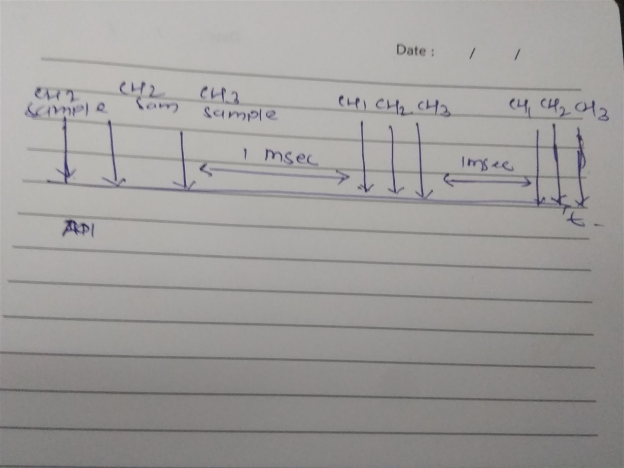
    in my application what i have to do is. i take the three sample from three different channel for every 1 msec . what should i have do in my code.

    sampling frequency that i have set is 50000 for getting 1msec time and 1khz frequency but still i dont get the 1 msec time and 1khz frequency on DSO.

    i am attaching the screenshot b elow. that you will understand what i have to do.

  • So what you want to do is:
    CH1 one sample, CH2 one sample, CH3 one sample, wait 1 ms, repeat?

    If that is the case you can't use the adcbuf driver since this is intended to be used to take multiple samples on one channel.

    Since nor the driver or the hardware is designed with multi channel in mind you have to open/ close the driver for each channel.
  • thanks for the quick reply.
    what is the max sampling frequency that i can set. is there any document available for the adc if you know then please tel me.
  • Hi
    how i can execute the one shot mode repeatedly in code. because i want to use 3 channel, from one shot mode i got the three channel data. but i want repeat this action again and again.

    please guide me about this issue.
  • hi,

    i am attaching my code below. in which i have call the adc convert function in the timer callback function. with one shot mode.

    i have set the timer 1 msec . for every 1 msec i want three channel samples at a time. that's why i am calling this function in timer callback function.but the problem is that, at only one time the callback function has been called if adc convert function called in timer callback function.

    but when i remove this adc convert function, then timer callback function working and called for every 1 msec.

    so i just want to ask that is there adc using its own  timers for the callback operation. because i have change the timer also but still the problem has been occured.

    so if you have any solution for this please suggest me . i want three samples from three different channels in one single buffer for every 1 msec .

    // calling this function for the 2 channels
    void timerCallback(GPTimerCC26XX_Handle handle, GPTimerCC26XX_IntMask interruptMask)
    {
        // interrupt callback code goes here. Minimize processing in interrupt.
        PIN_setOutputValue(pinHandle, Board_PIN_LED1,!PIN_getOutputValue(Board_PIN_LED1));
           //ADCBuf_adjustRawValues(handle, completedADCBuffer, ADCBUFFERSIZE, completedChannel);
                ADCBuf_convert(adcBuf, &continuousConversion, 1);
                memcpy((unsigned short*)&adc.usAdcResult[adc.ucAdcChIndex], (unsigned short*)continuousConversion.sampleBuffer, sizeof(unsigned short));
                memcpy((unsigned short*)&adc.usAdcResult[++ adc.ucAdcChIndex], (unsigned short*)continuousConversion.sampleBuffer, sizeof(unsigned short));
                   sprintf(uartTxBuffer,"value : \n");// adc.usAdcResult[adc.ucAdcChIndex]);
                   UART_write(uart, uartTxBuffer, sizeof(uartTxBuffer));
           SquareAddSample();
           /*********************************************************************************************/
    }

  • Hi Nilesh,

    Looking at the code snippet, are you using both UART and ADCbuf in callback mode? If any of these are operating in blocking mode, a call to these function within a callback context would lock the system.

    I don't know how the rest of the program is structured, but I think you are better of with moving this out to a task context. You seem to be doing quite some processing and this is not always a good idea to do within the callback context.

    In task context, it could be as simple as:

    while(DoReadings) {
       // Take readings
       ADC_convert(ADC1, buf[0]);
       ADC_convert(ADC2, buf[1]);
       ADC_convert(ADC3, buf[2]);
    
       // Do processing
    
       Task_sleep(1000 * 1000 / Clock_tickPeriod);  // 1 ms Task Sleep
    }

    If you need the delta time between samples to be 1 ms you could extend with a dynamic sleep time and use system timestamps.

  • thanks for the quick replay,

    i understand ,what you have mentioned above,but my application is on low power consumption .In that case procedure is that , initially my controller in shutdown mode for 4 sec. after it wake up by timer event ,then do the ADC sampling for 3 channel in 800 msec . and now it goes into ideal mode. and it will wake up by receiver interrupt and transmit the data in 200 msec . and again goes into shutdown mode after data has been transmitted. this is the cycle.

    so in that case i cannot call this function in while loop. and it is based on interrupt so for the ADC a 1 msec sampling period is required.
  • Hi Nilesh,

    With shutdown mode, do you mean standby? When the device is in shutdown mode, only external interrupts can wake it up again.

    In this scenario, I would not imagine your power consumption to be much difference doing this is Task context or not. If the ADC is in use, the device will be prevented from entering standby at all. If you are using callback or blocking mode won't matter.

    Doing a Task_sleep(some time) will result in the device going in to standby if allowed by the TI-RTOS. All in all, I would expect the overhead related to doing this in Task context vs using callback mode should be nearly none.

    If you want to really save power here, have you looked into using the sensor controller to perform the ADC readings and wake up the M3 only when to transmit the data?

  • hello sir,

    if i call the three function in while loop, also i have another function in while loop to perform another operation . in that case i required more time to complete the cycle. so in very time critical application , this logic would not better.

    if you know any another solution on it . so please tell me.
  • Hi Nilesh,

    As long as your task priories are set right you should be OK. However, callback mode will also work if you prefer that, you just have to be careful about the whole "blocking calls in callbacks" situation. Also, keep in mind that sprintf and similar functions takes a long time as well.

    I would also like to give the Sensor Controller another shout out, I think it might be a good fit if you want well timed ADC readings that is not impacted by the TI-RTOS application. You could in this case do all the readings and light processing on the sensor controller and when you have enough data pass it over to the CM3 (main CPU) to do the final processing.
  • hi sir

    in datasheet mentioned that sampling rate 200 KS/s. why it is fixed . how we can calculate it.
  • The datasheet state that the sampling rate is max 200 k. This is not a fixed variable.
  • ok, if i want set the 500khz sampling rate. what is the proper formula to calculate the sampling rate.
  • Hello Nilesh,

    as TER has wrote, 200kS/s is a max.
    The max can be achieved under a set of conditions and constrains.

    If your goal is to minimize an energy usage you should redesign your s/w and use SC (Sensor Controller).
    After a SC job is done (3 conversions finished) your main CPU would wake up and in one shot you would be able to read results from a shared memory. At least, 10 times less energy usage than your current approach.