This thread has been locked.

If you have a related question, please click the "Ask a related question" button in the top right corner. The newly created question will be automatically linked to this question.

CC3200MOD: SOP2 Input Current

Part Number: CC3200MOD
Other Parts Discussed in Thread: UNIFLASH, CC3200

Hello team,

I am supporting an application where there seems to be an issue with the SOP2 input current on our design, it was our partner's understanding that the SOP2 pin is configured as an input on power up and is sampled on the rising edge of nRESET to determine if the part should switch into UniFash programming mode.

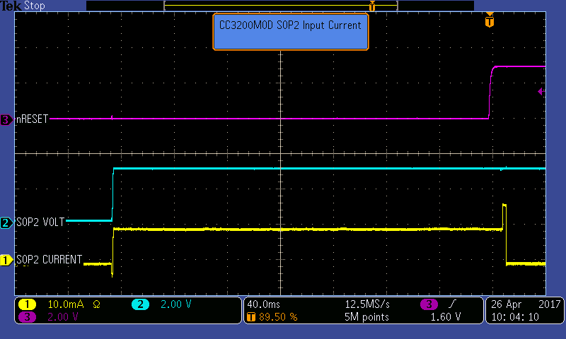
The current measured is around 10 mA from our 3 V supply into the SOP2 pin (see the scope shot below).  

Q: Is this the way the part is supposed to work?  Is there a way to reduce the current?

  • Hi Victor,

    What is the resistance of the pull you are using?

    -Aaron
  • Aaron,

    I am still waiting for a verification, but assuming that it is the recommended value, 2.7 kΩ, is this the way the part is supposed to work? Is there a way to reduce the current?

  • Aaron,

    I have gotten confirmation that it is indeed a 2.7 kΩ resistor, below you can see how the SOP2 is connected in two of the three prototype boards.

    In order put the third board into UniFlash programming mode I need to connect it as below, the scope shot from the original post was made with this setup.

    Q: Is there something that could have been done to change the operation of SOP2 on power up?

  • Hello team -- here is some further information provided to us:

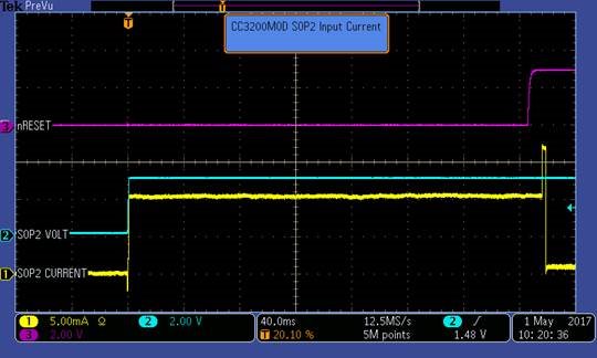
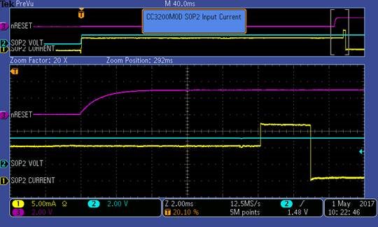
    "Power is being applied 80 mSec into the scope trace shown below.  After another 300 mSec the nRESET input to the CC3200 goes high (3.0 V).  Ten mSec after nRESET goes high the current being sourced from the 3V supply into SOP2 increases from 10 mA to 17mA for about 3 mSec.  The current then drops to 1 mA.  I believe this current is flowing into R14 in the circuit below.  It appears that SOP2 is powering up into the output mode and does not get switched to an input until 13 mSec after nRESET goes high."


    Q: Is there something we could have done to change the operation of SOP2 on power up? 

  • Hi Victor,

    As stated in the datasheet, during reset SOP 2 is hi-Z, it is an input to sense the state of SOP 2, and an output after power up.
    I believe this explains the 3 state of the SOP pin as shown in the captures.

    Adding the 270R current limiting pull-up resistor should help resolve this.

    Regards,
    Charles O
  • Charles,

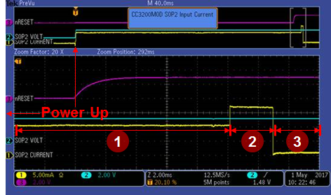
    Thanks for your reply -- I have a follow up question, if nRESET is active (i.e. nRESET = 0) and the pin is in High-Z why would the current be 11 mA? (it should be ~1.0 mA since that is the current running throught the 2.7 kOhm resistor) -- I was also wondering if you could describe what happens in each state (that is 1, 2 and 3, as pointed in the screen cap below) it would seem like the pin goes to Hi-Z after around 13 mSec of nRESET going high because that is when the current goes to ~1 mA

    Q: Is this the expected behaviour? could you explain what you believe is happening here?