This thread has been locked.

If you have a related question, please click the "Ask a related question" button in the top right corner. The newly created question will be automatically linked to this question.

CC3220: Uniflash problem with new custom board give error FS_ERR_FAILED_INIT_STORAGE when attempting to flash

Part Number: CC3220

I have been debugging my new PCB which is a direct leverage of the TI CC3220 reference design including the external serial flash.  When attempting to flash the board in order to get it into development mode I receive the following error from Uniflash 4.1:

Operation failed: fs_programming error: ret: -10332, ex_err: 4071 - FS_ERR_FAILED_INIT_STORAGE

Anyone have any information on what this could mean?

Thanks for your help,

Mark

  • Hello Mark,

    When you press 'connect' in Uniflash, the right hand side of the UI should show some connection status about the device and about the serial flash status. Could you tell us what that UI shows, in-particular, the flash codes that are reported please?

    ~roger

  • roger,

    Thanks for the quick reply.  I'm seeing 0x0,0x0,0x0 in the flash codes ...

    Mark

  • Hi Mark,

    Ah, ok.

    Could you please try booting the board with SOP[2:1:0] pins set to 0:0:0, let it run for some time (30 seconds), then switch back to SOP[2:1:0] pins sets to 1:0:0 or 0:1:0 and try to reconnect again with uniflash to read-back the flash codes?

    ~roger
  • roger,

    I booted with 0:0:0 and let the processor run for 30 seconds and then switched the pins to 0:1:0 and still get 0x0,0x0,0x0 ...

    Mark
  • Ok, thanks for trying that.

    Next step I would recommend would be to get a logic analyser on the SFLASH signals and try to get capture of the transactions on the bus.

    Have you ever been able to program this board? Was anything programmed into the SFLASH before it was mounted on the PCB? Do you have any other boards to try this on? Do you have the ability to attach an external SFLASH programmer (as we have on the launchpad)?

    ~roger
  • I have scoped out the signals and everything looks OK but I'll get you a more complete answer to your questions in the morning.

    Thanks for your help.

    Mark
  • Roger (or anyone),

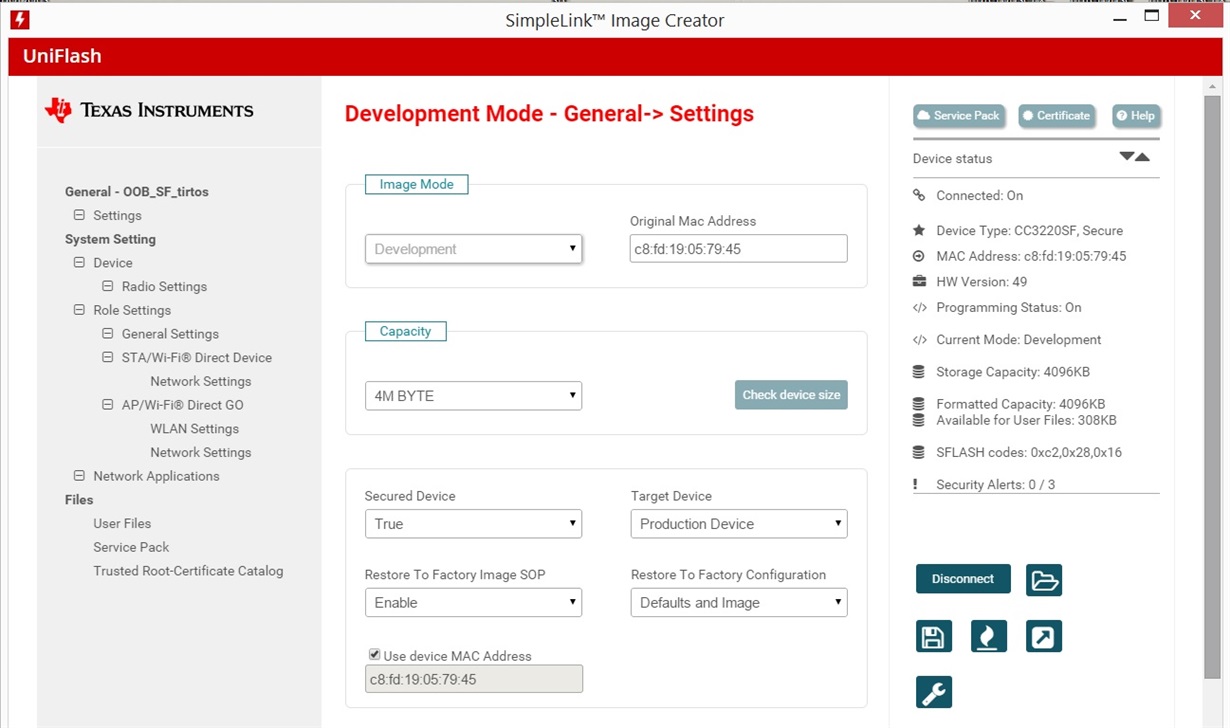
    I have straightened out a board issue relating to the Flash and now am able to program my board with the OOB provided with the SDK.  I have noticed 2 things:

    When booting only a small amount of flash is read and then the unit hangs.  When I try and debug my sample tirtos app the CC3220 does not breakpoint at the main but instead seems to be trying to execute code at 0xFDAA.  If it telss you anything, I do not see the DC_DC_PA_SW activating ...

    Below is my UniFlash window after programming:

    Any thoughts?

    Thanks,

    Mark

  • Hi Mark,

    Great - glad you got the flash sorted.

    Just to clarify, you said you were able to program the OOB project - are you saying that the OOB project works ok, but your own sample app does not?

    I would suggest programming a uniflash project that is configured for development mode, but doesn't have an mcuflashimg.bin included, so that it doesn't start to boot an application at startup.

    Could you try building and loading one of the driver examples, such as uartecho and let us know if that runs reliably?

    ~roger
  • Hi, Roger,

    No, the OOB project does NOT work.  I see a short burst on the Flash at bootup and then nothing.  When I look at the LAUNCHXL there is a considerable amount of Flash activity and the DC_DC_PA_SW goes active and VDD_PLL gets turned on. 

    Do I need to configure anything differently (other than I/O) since I am using a custom board?  VDD_RAM is OK and the VDD_DIG is OK.  I have verified that the SOP signals are correct at the de-assertion of reset.  I have studied the schematics closely and my design matches the reference design pin for pin.  The only difference is that I am running at 2.5V Wide Voltage mode.

    Mark

  • Hi Mark,

    Ok. So, I'd definitely suggest a uniflash project without an mcuflashimg.bin to start with (maybe just remove it from the OOB demo), and then connect with CCS to inspect memory and run further system tests from there which should give us more clues.

    Are there any significant layout differences vs LAUNCHXL? Is this a 4 layer board?

    ~roger
  • I'll try that in the AM.

    This is a 2-layer board but with very robust power supply design so I don't have any doubts about that.

    Is there a document that outlines the boot sequence and might explain why the initial boot from Flash is failing? Are there any UART messages sent that may give us a hint? When I run my version of sample_publish_connect it never gets to the main_tirtos breakpoint ...

    Thanks for your help,

    Mark
  • Roger,

    I now have 2 boards up and running and doing the same thing. Could we possible have a phone conversation today to see if there is anything amiss? I am approaching a deadline and although I appreciate the email support, it does tend to be slow.

    Just to be clear on what I have been doing with the CC3220 LAUNCHXL board, I loaded the board with OOB demo (in order to put it in development mode) and then have been debugging code derived from the IoT samples. Those all work on the LAUNCHXL board. I was hoping that that was all that was required for my new board, but apparently something is missing that will not allow the code to breakpoint.

    Best regards,

    Mark
  • Hi Mark,

    Here'a a couple of things I'd suggest that might be useful.

    1. Given you are able to access the debugger, this means you've got the serial flash programmed successfully and have a valid image that has put the device in development mode. This process requires a substantial amount of the system to to functional, so I think that's good news.

    2. If your code is running, but not reaching main(), it sounds like there may be a problem somewhere during initialisation of the runtime system, which may point to an application configuration problem (linker/memory/map), or a memory problem.

    2a. Try a quick internal RAM test, by using the CCS memory 'fill' [ Tools -> Fill Memory ] to fill all the internal SRAM [0x01000000, length 0x10000/4 words] with some test patterns and inspect in the memory view. [ Note, given (1), I doubt this will show anything, but worth a quick check ].

    2b. Try loading the code again, but disable the auto-run to main. [ Tools --> Debugger Options --> Auto Run and Launch Options [ Auto Run Options, Run to 'main' On program load/restart ]. This will allow you to single step through the initialisation code from the entry point (_c_int00) to see where the code breaks and if it is possible to reach main() by slowly single-stepping. If there is a common failure location, please make note of the opcode and addresses to see if this gives some clues.

    3. Try loading code into RAM instead of FLASH to eliminate any potential issues with the FLASH or system noise. You can do this by changing the linker command file to move all sections from FLASH->SRAM in the linker and in the tirtos configuration. The easier way though is probably to use one of the 3220S examples, instead of the 3220SF examples, since these are already configured in this way.

    Hope that helps to home in on the problem,
    ~roger
  • Roger,

    Many thanks for your insightful and extremely detailed guidance in investigating this problem.  My board was in fact failing under step 2b during RAM initialization from the internal Flash.  Running several example programs from the CC3220S demos proved this and ran reliably.  Subsequent rebuilding of our App (based on one of the AWS applications) ran perfectly and we were able to make great progress on debugging most of our hardware.

    The failures would appear to be due to the use of a 2-layer board and inadequate control of noise on the noise-sensitive VDD_DIG power supply.  We do have very tight cost restrictions on our consumer device but more careful layout of this circuit combined with going to the CC3220S part will hopefully address the problem.  I do understand that there may be issues ahead during FCC testing and that may ultimately force us into a 4-layer board.

    When designing the original circuit, I did not understand that the AWS code required the external Flash and assumed that the SF part would be adequate.  Since the external Serial Flash IS required, we can use that with the CC3220S and successfully deploy our product. 

    A final tip of the hat to Roger for his knowledge and experience in digging in to our problem and guiding us to a solution.  Cheers to you!!

    Mark


  • Hi Mark!

    Great work - really glad you've made good progress here and are able to continue now - it's impressive you've been able to design a 2 layer board that works so well! - it does make sense though that the on-chip flash might be the first part to be susceptible to any noise on the power-supply. As you mention, I suspect you'll be able to continue with software development using this board now, treating it as an 'S' part - but I'd definitely advise a 4-layer board design for your next spin, so that we know we can support you to achieve product level certification.

    If you need to use a 2-layer board for the rest of your product, it might be worth considering one of the modules (www.ti.com/.../CC3220MOD), which could easily be mounted on a 2-layer board. The modules also include the serial flash internally.

    ... and yes, you're absolutely right - we should be more explicit that all CC3100/CC3200/CC3120/CC3220 QFN based designs require an external serial flash, (note, this is not specific to the AWS examples), thanks for highlighting that for others.

    Cheers + good luck with the project!
    ~roger