This thread has been locked.

If you have a related question, please click the "Ask a related question" button in the top right corner. The newly created question will be automatically linked to this question.

LM2679: Significant voltage drop when under load

Part Number: LM2679
Other Parts Discussed in Thread: ASH, TPS2420

Hi all,

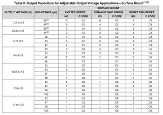
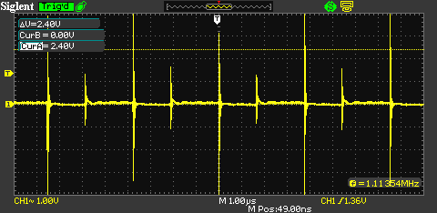
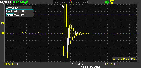
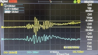
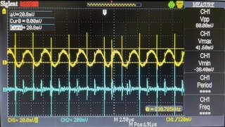
Just finished the assembly of a few prototype boards and have encountered the following issue. While the circuit correctly outputs 7.4V ±0.1V while not under load, when a 0.6A load is applied the output voltage from the LM2679 drops to around 6V.

Fortunately though the 6V output will still work for our application but we would like to sort this issue out.


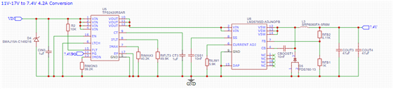
Attached below are the schematic, board layout, components and images from a scope reading the output voltage.

Component Values:

IC: LM2679SD-ADJNOPB
Cboost: 10nF
CSS: 10nF
CIN: 2X 56uF
COUT: 2X 47uF
RFB1: 1K
RFB2: 5.11K
RLIM1: 5.9K
Inductor: 22uH 60mOhm


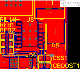
Any help would be greatly appreciated as we are looking to get these boards into production soon, Thanks!
Ash

  • HI

    1. I didn't see Cin in your schematic, and inductor value is 22uH or 22mH?

    2. what is the Cout3 and 4 voltage rating, pls follow datasheet recommend:

    3. the layout of power stage is not good, we recommend keep AC current loop  which is Vin cap->Vin PIN->SW->diode GND->input cap GND as small as possible, but from you layout, the diode GND is not close to input capacitor's GND.

    Thanks

  • Hi Daniel,

    There are 2x 56uF caps on another page on the schematic, they are located right next to the input efuse on the board. The inductor is also 22uH not mH (apologies).

    The Cout 3 & 4 capacitors are 25v rate MLCC’s.

    The input capacitors are also placed on the board below the the image, they connect directly unobstructed on the same layer to the gnd of the diode. I’m not at my computer for the next 12 hours so I can’t send you and image of it but the input efuse protection is below the voltage converter.

    Thanks,
    Ash

  • HI Warren:

    can you help confirm that the input cap  at the input of efuse or output of efuse?  cause the input cap need to close to the LM2679, and you can also monitor the input voltage of LM2679, see any oscillation on the input pin

  • Hi Daniel, the input caps are at the input of the efuse next to the DC input, there is a direct connection between the output of the efuse (TPS2420) and input of the LM2679. The attached images from the scopes also show the output of the LM2679 (CH1) and the input voltage (CH2).

  • Hi Daniel, please see attached:


    12V Supply used with 0.6A supplied to the circuit. - Known good power supply, issue also occurs on other supplies.

    I have also tried this with another load device and the performance of the LM2679 becomes even worse dropping to 4.8V! with the same 12v 0.6A supplied voltage and current.

    1. Input pin of the LM2679 - 1.00μs
    2. Input pin of the LM2679 - 50.00ns
    3. (CH1) Input of the LM2679 | (CH2) Input capacitors of TPS2420 - 25.00ns


  • Hi Daniel,

    After reading a few other issues with transients and oscillations when under load we figured there was an issue with the board layout, sure enough there was an issue that the drc did not pick up and the RFB2 resistor was connected to the input side of the inductor and not the output. After cutting the incorrect trace and soldering a bodge wire we saw a maximum voltage drop of 0.2 under a 4A load.