This thread has been locked.

If you have a related question, please click the "Ask a related question" button in the top right corner. The newly created question will be automatically linked to this question.

TMS320F28379D: Teknic motor connections/encoder connection issue during fast control loop (FCL) testing Level 2

Part Number: TMS320F28379D
Other Parts Discussed in Thread: LAUNCHXL-F28379D, BOOSTXL-3PHGANINV, 2MTR-DYNO

Hello,

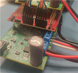
I have a LAUNCHXL-F28379D / two BOOSTXL-3PhGaNInv connected to two Teknic motors(2MTR-DYNO) , I think the exact motor part number is Teknic M-2310P-LN-04K

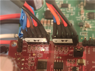
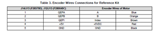
The encoder interface is connected to the launchpad via the J14(QEPA for M1) and J15(QEPB for M2) headers .

We are trying to run the dual axis motor control  project mentioned in this document :

www.ti.com/.../spraco3.pdf

I have powered the launchpad via the inverter board(J5 on one of the BOOSTXL-3PhGaNInv) is populated. And Jumpers JP1-JP5 are removed from the LAUNCHXL-F28379D, JP6 is populated for 5v supply.

During testing in Build level 'FCL_LEVEL2' I am able to spin the motor, but I don't see any feedback from the encoder? (motorVars[0].ptrFCL->qep.ElecTheta is always 0)

This is what I have done so far:

1. Set enableFlag to 1.(The motorVars[0].isrTicker counter starts incrementing)

2. Set 'motorVars[0].ctrlState' to CTRL_RUN which sets 'motorVars[0].runMotor' to MOTOR_RUN

3. Set motorVars[0].speedRef to 0.15, Vqtesting to 0.1 and Vqtesting to 0.

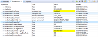
Also motorVars[0].ptrFCL->lsw is always stuck in ENC_WAIT_FOR_INDEX state.

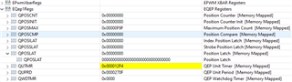
The QPOSLAT register is always 0.

I also physically checked the voltage at the QEPA header, The index pin is always 5v,Should'nt the encoder pull it down to 0 when there is no index?

The above is true for the other motors also.

Thanks

  • Please if  the J4 of the motor is connected to the J14/J15 on LAUNCHXL-F28379D, and make sure that the order is correct as J14-PIN5/GND->J4/BLACK,  J14-PIN4/+5V->J4/RED, J14-PIN3/QEPI->J4/BROWN, J14-PIN2/QEPB->J4/ORANGE, J14-PIN1/QEPA->J4/BLUE.

  • Hi Yanming,

    Yes that is how I have connected J4, Have a look.

    I have connected the the connections according to the datasheet:

    One more point I have left the P DRAIN(Pin 1 of Molex connector) floating, Is this an issue ? Because I see 5v difference when measuring the potential difference between the Motor body and GND ?

  • Can you use an oscilloscope to check if outputs of the A/B/I are correct on both connectors to the encoders in build level 2? And try to run one motor first to see what happens?

    Did you remove R20 on BOOSTXL-3PhGaN board as shown in design guide?

  • Hi Yanming , I solved the issue, it was the cable issue.

    There was an issue with the dual lug connections of both the wires. Dual lugs are present in the 5v and GND connections, The crimping was not properly done and there was no continuity in one of the ground wires.