This thread has been locked.

If you have a related question, please click the "Ask a related question" button in the top right corner. The newly created question will be automatically linked to this question.

LDC0851: Designing tiny sensor PCB of 3mm using LDC0851

Part Number: LDC0851
Other Parts Discussed in Thread: LDC1312, , LDCCOILEVM

Hello Team,

      we want to develop inductive encoder with quadrature output using LDC0851.The dimension for target PCB is OD-45mm and ID- 42mm . we have space of 3mm to design target PCB.

We will plot 8 slot on target PCB for 32 position ( will be using 2 LDC0851 for quadrature output). Now the main part is sensor design. we want to consider parameter for sensor design from below forum i.e 2mm sensor design .

https://e2e.ti.com/blogs_/b/analogwire/posts/inductive-sensing-how-to-use-a-tiny-2mm-pcb-inductor-as-a-sensor

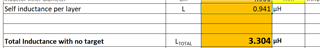
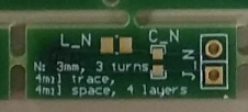
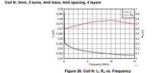
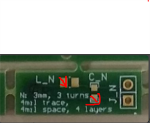
I am clear that you have used 4 layer, 3 turn that gives 150nH inductance and additional you have used 47uH inductance. this 4 layer is only for sensor coil.

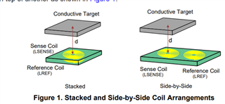
for LDC0851 it requires two coil reference and sensor . there are two options 

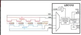
1. stack up - first two layer I will used for sensor and last two for reference. for higher inductance I was thinking of placing 4 sensor with series combination like  (LDC1312 incremental Encoder Knob 32 position)

below will sensor position placement for 2 LDC0851

2. side by side - for this all 4 layer will will be sensor and side by 4 layer will be reference . for this is it ok if I plot 4 sensor and 4  reference for higher inductance in series combination.

for series combination I will use above sensor position but then what will be position for reference coil.

can you suggest which option will be better.

Regards,

Sayali

  • Sayali,

    Thanks for the inquiry.
    Is it possible to provide simple diagrams - or references to diagrams in the user's guide - of the two options you are considering?

    Regards,
    John

  • Hello John,

      Please consider below diagram of two options i.e stacked and side by side and for detail I have attached one document .

    LDC0851 Stacked Coil Design Considerations.pdf

    if we select any of above two options ,to increase inductance I was thinking of using  multiple series inductors. as shown below for LDC1312

    instead of 3 turn I will make 2 turn and use multiple series inductor. Please let me know is this is acceptable for LDC0851.

  • Hello John,

            Is there any formula to calculate inductance from geometry input like sensor dia . in user guide the formula is based on frequency(below snapshot)

    but in excel tool we first put geometry input like ID,OD, no of turns, shape then it calculate inductance and frequency.

    wanted to know exact formula for inductance based on geometry.

    even please elaborate relation between self and total inductance in excel tool

    Regards,

    Sayali

  • Sayali,

    The expressions used in the tool are very similar to the ones described in an an IEEE paper.

    The self inductance per layer is the inductance of a spiral on a single layer while the total inductance covers the total over the multiple layers that make up a single inductor. The total inductance s not a simple sum of the single-layer inductances.

    Regards,
    John

  • Hello John ,

      Thanks for information.

    will check and let you the feedback.

    Regards,

    Sayali

  • Hello John,

            we did some experiment with LDC0851EVM , below are details of it.

    1. we removed below  existing sensor reference coil(stack configuration) (20mm dia)

    2. In place of above coil I placed OD-3mm, 3turn coil(below is snapshot of same) for both sensor and reference in side by side configuration

    3. when I separately measure inductance on above PCB (i.e OD-3mm, turn-3) it gives 4 uH and as per user guide of LDCCOILEVM the highest inductance is 0.28uH.

    4.after configuring sensor  and reference PCB in side by side config with LDC0851(snapshot below), it gives require output means i.e by placing metal over sensor output goes low and LED is ON otherwise it is high and LED is OFF

    5. as per one of the forum of using tiny PCB (https://e2e.ti.com/blogs_/b/analogwire/posts/inductive-sensing-how-to-use-a-tiny-2mm-pcb-inductor-as-a-sensor) we need to place additional inductor in series . but in my case when I put 4.7uH inductor in series with coil PCB ,the output is always low i.e LED is always ON whether target is present or not.

    6.can you help us to identify inductance range for LDC0851 with small sensor and reference coil in side by side arrangement .

    7. we want to design encoder using LDC0851 with tiny sensor coil arrangement and our calculation and practical results are not matching with your excel tool.

    Regards,

    Sayali

  • Sayali,

    The first step is to confirm your connections between the EVM and the sensor coils.

    Also, one of the best practices is to keep connections as short as possible due to parasitic inductance & capacitance.
    Please try shortening your wired connections, and if possible, make them twisted pairs. 

    Regards,
    John

  • Hello John,

    With above connections I am getting required output, and better performance we will keep connection as short as possible ,the question is about inductance of coil.

    what should be inductance of this coil (OD-3mm,turn -3, 4mil trace and space , 4 layer. We have taken this coil form LDCCOILEVM. when we measure inductance across highlighted red point we get 4 uH(micro henry)

    but as per excel tool for spiral inductor we didn't get this value. We want to know the range of sensor PCB using small geometry spec (OD-3mm,turn -3, 4mil trace and space , 4 layer) for LDC0851 sensor.

    Regards,

    Sayali

  • Sayali,

    What is meant by "range of sensor PCB using small geometry spec"?
    Does this refer to the distance between the target and the sense coil when using the approach in the tiny sensing coil blog?

    Regards,
    John

  • Hello John,

      The range of sensor means min and max value of inductance of sensor PCB. I referred the blog of tiny inductor , in that as the inductance of 2mm OD,3 turn , 4layer is 150nH . as the inductance is low they have added 4.5uH in series.

    In our we case we have used your design PCB from LDCCOILEVEM i.e serial N no.(OD-3mm,turn -3, layer 4). When we physically measure the inductance of this PCB it came to be 0.4uH (0.0004mH). as this inductance is also low we have 4.7uH in series and test with LDC0851 evaluation board . when we give supply the LED is always ON irrespective target is present or not. so we removed the external 4.7uH inductance , then start working properly. when target is not present LED is off ,target is present LED is ON.

    I wanted to know what is inductance value of PCB from LDCCOILEVEM i.e serial N no.(OD-3mm,turn -3, layer 4). 

    for LDC0851 what will be inductance range is acceptable of this PCB .

    it would be better if we can connect over the call like teams or google meet so that I can explain in details , this is taking time and our project is getting stuck.

    Regards,

    Sayali

  • Sayali,

    Please be mindful of the min/nominal/max sensor parameters given in the LDC0851 data sheet:

    The table shows a minimum inductance of 1.8uH or 2.5uH dependent on the power supply.
    It also gives a typical/max sensor frequency of 19MHz, which is probably easy to achieve or exceed with a small inductor.

    The (below) plot of coil N's L and Rp from the LDC Reference Coils User’s Guide shows it is about equal to the minimum inductance.

    So it would be okay to add a little series inductance. while at the same time adjusting your C to be sure the measured sensor frequency falls below the 19MHz upper limit.

    Be sure to account for the pin parasitic capacitance (as you choose the L, C, Fres values, and also consider the Ctotal as shown in the table. 

    The spreadsheet tab LDC0851_calc can help with the calculations. Please give this a try and let me know if you have any questions.

    Regards,
    John

  • Hello John,

      Thank you for reply.

    I understood the range specified in the datasheet. when I connect no external series inductor on N coil the inductance measure with LCR meter is 0.4uH which is very low and sensor capacitance on LDC0851EVM eval kit PCB is 68pF. but still I am getting required with this low value. this value does not fit in the range specified in datasheet of LDC0851.

    want to confirm what is exact value of inductance of N coil. and when I try to validate this value in LDC_Tools-ext51 it is not matching.

    it is showing high sensor frequency increase L or C. for reference I have again attached that sheet.

    I will use coil as it is with no series external inductor , but want to due less inductance still I am getting required result.

    Regards,

    Sayali

    LDC_Tools-ext51.xlsx

  • Sayali,

    I have a few questions:

    1. When you measure the N coil's inductance, do you know what frequency the LCR meter uses?
      I am asking this because a coil's measured inductance can vary over frequency due to the measurement set-up
    2. What sensor frequency do you measure with coil N and the 68pF cap?
      If you use an o-scope to measure this, be sure to use high-impedance probes and - if you can - have a 1k resistor between the probe tip and the test point on your PCB.

    regards,
    John

  • Hello John,

      I have measured inductance by keeping 10Khz frequency . Is it possible to verify at your end ?

    I am getting 48MHz frequency. positive side of probe is connected to LS and negative to com. let me know if checking in wrong manner.

    have you check my excel sheet of inductance value calculation ?

    Regards,

    Sayali

  • Sayali,

    Your sensor frequency sounds a bit high.
    Can you try reducing your sensor frequency closer to the typical max (= 19MHz) by increasing your sensor capacitance?
    The tool predicts doubling your capacitance will bring the sensor frequency to what you are actually measuring. 
    I think this implies you may have some non-trivial parasitic capacitance that may be of a similar magnitude to your sensor capacitance.
    That will need to be considered in your experiments.

    Regards,
    John

  • Hi John,

    I tired to increase the frequency but while doing so my board got damage ,will perform this experiment when new board arrives.

    till then can you comment on my excel sheet of inductance value calculation share earlier. wanted to confirm exact value of inductance of N coil. and recheck with excel tool.

    Regards,

    Sayali

  • Sayali,

    If you look at frequency-dependent plot for coil N, you see the inductance varies over frequency, which is normal.
    You might also notice the inductance is much larger at lower frequencies, like your LCR meter uses.
    The spreadsheet calculator does not fully model this behavior.

    The other spreadsheet we provide - Excel_FEMM_v1p29.xlsx - runs FEMM EM simulations in the background to compute estimates of the coil values, which then appear in the spreadsheet's output fields. The spreadsheet also expects you to save the FEMM simulation file it creates based on your inputs to your desktop.
    You will need to have FEMM installed on your machine for this to work. You can access the FEMM downloads and installers here.
    Note that you will need to enable macros for the Excel to run FEMM. 

    A quick substitution of your coil parameters into the FEMM spreadsheet resulted in an inductance of 0.3243uH, which is much larger than the equation-based spreadsheet's answer (= 0.188uH), and a little larger than what is shown in coil N's plot.  

    Based on these considerations, two things to try are:
    1. Measure the coil inductance near or at the expected sensor resonant frequency.
    2. Use the FEMM-based spreadsheet to calc the inductance based on the coil's mechanical parameters.

    Regards,
    John