This thread has been locked.

If you have a related question, please click the "Ask a related question" button in the top right corner. The newly created question will be automatically linked to this question.

TPS2549Q1EVM-729: Supply 5v externally

Part Number: TPS2549Q1EVM-729
Other Parts Discussed in Thread: TPS2549-Q1, , TPS2549

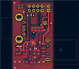
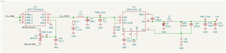
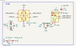
I'm designing a board based on the tps2549-Q1 and try to understand it by using the TPS2549Q1EVM-729. 

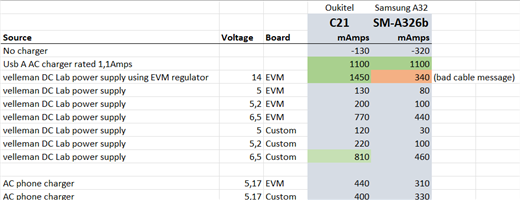
If I supply 12 volts on j3, my phone (oukitel c21) charges as expected with 1,5A

If I work around the internal voltage regulator by supplying 5v on J4, and GND on J3, as is described here:

https://e2e.ti.com/support/power-management-group/power-management/f/power-management-forum/980505/tps2549q1evm-729-tps2549-only-operation

It only charges with 400mA, 

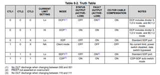
Its running auto mode, but changing the configuration DCP doest not change.

What am I missing here?

  • Hi Bjorn,

    Could you please help confirm where your VBUS comes from based on J2 and J4? A direct 5V power source or a typeA power source.

    If a type-A power source is given, maybe we need to look into the power source capacity with J2.

    Best regards

    Shuai

  • I’m using a Bench power supply in both cases. So it’s the same for 12v as for 5v

    changing the voltage to 4,5 of 5,5 does not work either. What do you want me to check on j2?

  • Hi Bjorn,

    I tried with the TPS2549Q1EVM-729 in lab. 

    The behaviors with internal 5V or external 5V power supply are the same.

    I just used 5.2V on TP2, GND on J3 GND. A HUAWEI phone is connected to J1 by a type-A to type-C cable.

    The sink current from the phone is 1A the same as using J3 for power supply.

    Please notice the Max VIN  for TPS2549-Q1 is 7V, voltage higher than 7V may damage the device.

    Could you please try with another sink device to see the behavior?

    Best regards

    Shuai

  • Sorry for the late response Shuai,

    I’ll provide a little bit more context first about the project, and maybe you can point me to the right direction (or documentation).

    I already have a PCB prototype. It is a usb host device but does not provide enough amps for a phone to work for a long period of time. So for the next revision I’m planning to use the TPS2549.

    As a test, I designed a simple board based on the EVM-729, without the power supply because the main board provides power to usb with a LMR1403. This is the layout:

    When I did not got the desired amp results, I ordered the EVM-729 to see what I was missing.

    I created a small table, with measurements for different devices:


    Some notes:

    • The AC phone charger is a normal wall charger for benchmark
    • I used the Android app Ampere for measurements
    • The Samsung A32, does not accept the TPS2549, showing a bad cable message (used different cable’s, same result. No problem with the cables in a normal wall charger). Which is weird.
    • For your request for using a different source, I used an AC phone charger, and an usb-c breadout board to connect it to J4 & gnd with dupont cables.
    • Custom board in the table is the pcb board above

    Any suggestions or pointers?

  • Hi Bjorn,

    Could you please help share with your schematic about this prototype?

    Are you going to use TPS2549 or TPS2549Q1?

    There are different sink amps behavior with different phones, and this is reasonable. Different phone and different battery status may have different sink current status.

    Best regards

    Shuai

  • It's going to be the TPS2549Q1, sorry for the confusion.

    Can you give a little bit more detailed information what could cause amp difference between powering 14v on J3, and 5,2 on J4? Is it cable resistance? frequency or..?

    power supply looks like this:

    USB connector like this:

    powering the evm-729 directly through usb

  • Hi Bjorn,

    I think there will be no difference no matter with external power supply or just power the TPS2549Q1 with directly VIN.

    I have three question based on your test:

    1. Could you please help check the status of the control pins, CTL1/2/3?

    2. I'm note sure about the power supply when you use the USB connector. It means you use your USB connector to directly connect to J2 on EVM, right?

    3. Could you please try with more other different kind of phones for this current behavior? Because based on your test results, there are different sink currents event you just change different mobile phones.

    Best regards

    Shuai

  • Tests were in Auto switch mode (so no jumpers on CTL1/2/3), but with no host connected to the usb J2.

    Changing it to DCP/HI (jumpers on CTRL1/2) , does not change the results.

    I did some more testing, and today the Samsung did not report the "bad cable" message when suppling 14v to J3. I started charging nicely with 1.5A. which is weird. It is the same cable?

    When suppling 5.6v or lower to J4 or TP2, the samsung phone shows the 'bad cable' message again. Going above 5.6v, it doesn't show the message, but it still is charging around 250mA.

    2. I'm note sure about the power supply when you use the USB connector. It means you use your USB connector to directly connect to J2 on EVM, right?

    Yes, for prototyping, the idea is to follow the EVM schematics and incorporate it into the new board.

    3. Could you please try with more other different kind of phones for this current behavior? Because based on your test results, there are different sink currents event you just change different mobile phones.

    Using a Samsung Tab (SM-X200), I see similar results. 


    I think there will be no difference no matter with external power supply or just power the TPS2549Q1 with directly VIN.

    Well, something is different, because I'm seeing different results? 

  • Hi Bjorn,

    Shuai is out of office today. 

    Will reply to you tomorrow.

    Thanks.

  • Hi Bjorn,

    Thanks for your tests and update. Actually it's a really tricky case and tricky behavior with Samsung device,

    I need to do more tests to verify is there are any abnormal behavior. Also if you have the resource, you can also try with below directions.

    1. I will measure the OUT voltage from external J3 to see how this output (input for charger) will be.

    2. Further investigate if the cable compensation leads to this abnormal behavior.

    3. Make sure there is no D+D- connections with J2 and only power on J4. 

    Best regards

    Shuai

  • Hi Bjorn,

    I found the root cause for this case. It's related to the modes and also the DP/DM messages for Samsung phones.

    When DCP mode is chosen, no data communication is needed, and in this case you can find the Samsung phone could be charged.

    When SDP or CDP mode is chosen, valid data communication is needed, and in this case the DP/DM should be connected to the Host, then you could find the Samsung Phones can be charged with the correlated currents.

    Best regards

    Shuai