This thread has been locked.

If you have a related question, please click the "Ask a related question" button in the top right corner. The newly created question will be automatically linked to this question.

TPS63700: Incorrect Output Voltage

Part Number: TPS63700
Other Parts Discussed in Thread: TPS3700, INA2180

I am using the TPS63700 to generate a negative supply in a manner that relies on an external, variable reference instead of the reference provided by the VREF pin of the TPS63700. My reference's adjustment range is 0 V to +1.8 V. Interestingly, when my reference is at 1 V or less, the output of the TPS63700 tracks accordingly and its voltage agrees with equation 1 on page 13 of the datasheet. The feedback voltage is also at the correct value of 0 V when my reference is 1 V or less.

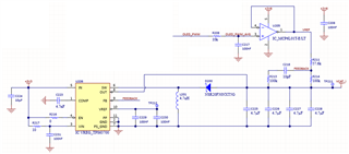
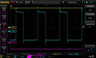
Once I increase my reference above 1 V, I see the feedback voltage begin to increase and the output of the TPS3700 remains at a fixed voltage, regardless of the value of the reference voltage above 1 V. I have attached a screenshot of my schematic for reference.

  • Hi Andrew,

    Thanks for reaching out.

    Can you probe Vin, SW, Vout and inductor current when you increase the reference above 1V?

    BRs,

    Bryce

  • Hi Bryce,

    Unfortunately I do not have a current probe to measure the inductor current. Here are the VIN, SW and VOUT waveforms for the reference below 1 V (0.7 V) and for the reference above 1 V (1.3 V), respectively:

  • Hi Andrew,

    One possible reason is that when external reference is higher than internal reference voltage, the reference is clamped. Can you help check VREF pin voltage as you change your external reference voltage?  

    If it is clamped, you can set the external reference voltage between 0V to 1V and change R211 and R214 ratio to obtain your target output.

    Regards,

    Mulin

  • Hi Mulin,

    When I adjust my external reference voltage over an arbitrary range of 0.7 V to 1.3 V, the VREF pin of the TPS63700 remains at 1.22 V. It is unclear to me how the TPS63700 internal reference circuitry is clamping the external reference from the description of operation outlined in the datasheet.

    Continuing my investigation, I experimented with disconnecting my op amp circuit, and instead used the TPS63700’s VREF pin (I connected TP212 to R211 in this case). Additionally, I changed R211 to 121 kΩ and R214 to 221 kΩ to meet the current sourcing criteria for the VREF pin, outlined on page 13 of the datasheet. This ratio should have set the output to -2.21 V. Instead, my output was -1.56 V; VREF was 1.213 V and I measured 220 mV at the feedback pin.

    This last experiment demonstrates the op amp circuit is no longer a variable.

    -Andrew

  • Hi Andrew,

    Did you take the U205 down when you do the last experiment?  If not, please take it down and see whether the output is normal.

    Regards,

    Mulin

  • Hi Mulin,

    Yes, I physically cut the op amp output's trace to disconnect it from influencing the TPS63700 circuit.

    -Andrew

  • I solved the issue: I had a INA2180 current sense amplifier connect to this rail that was causing the errant operation of the regulator.