This thread has been locked.

If you have a related question, please click the "Ask a related question" button in the top right corner. The newly created question will be automatically linked to this question.

DRV8873S-Q1EVM: Differences between MD006A and MD006B

Part Number: DRV8873S-Q1EVM


Tool/software:

Hi TI engineer,

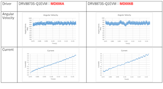
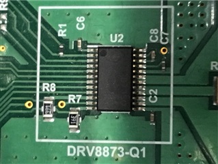
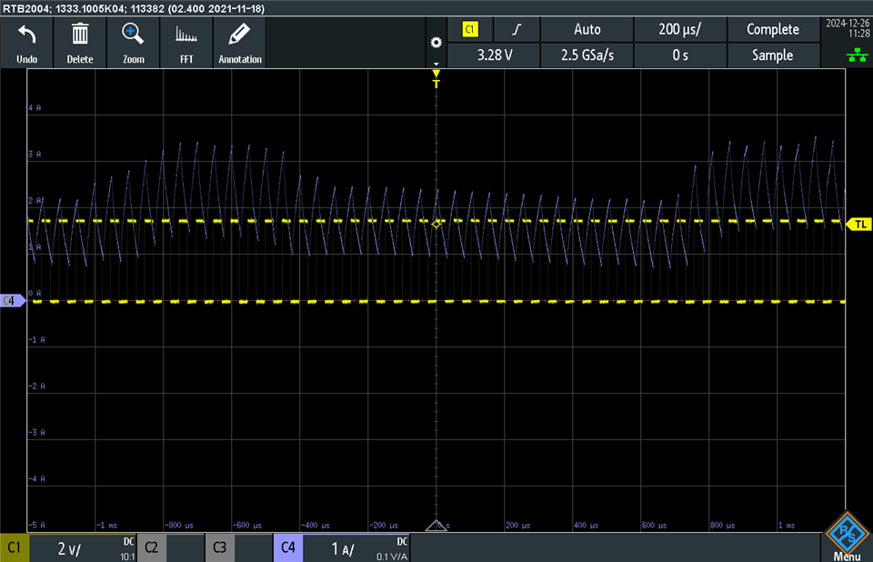
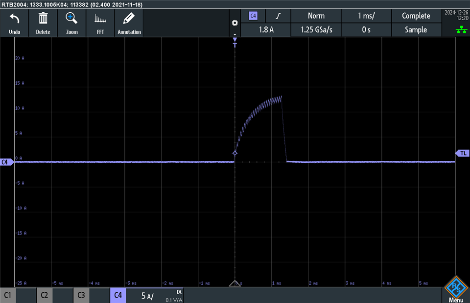
The DRV8873S-Q1EVM is used to drive the motor, and the current is measured by an external ammeter.
When we prepared 2 configurations of controller →DRV8873S-Q1EVM and measured the current of the same motor, there was a difference in the current waveform, and when we investigated, one of DRV8873S-Q1EVM was MD006A and the other was MD006B.

From the above, I would like to ask the following two questions.
・MD006A and MD006B Changes
・Is there a possibility that the motor current waveform changes between MD006A and MD006B?

(Supplementary Explanation)
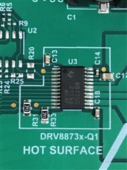
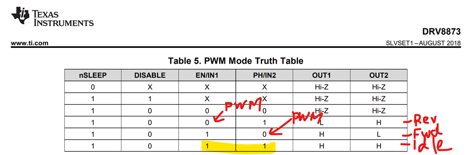
The PWM signal of the controller is connected to the pin near the center of the DRV8873S-Q1EVM and driven by PWM control.
The power supply is set to 7V/3A.

  • Hi Fujikawa-san,

    Give me 24 hours to look into this and get back to you.

    Best,

    Keerthi

  • Hi Keerthi,

    I hope this message finds you well. I wanted to follow up on the question I asked recently. Have you had a chance to look into it?

    Thank you for your help!

  • Hi Fujikawa-san,

    I am still looking into this as I am currently unable to locate the board files for version A. I will give an update tomorrow.

    Do you have some waveforms of PVDD, OUTx, INx  and current?

    Best,

    Keerthi

  • Dear Keerthi,

    Sends motor angular velocity and current waveform.
    Unfortunately, there are no PVDD, OUTx, or INx waveforms.

    There are differences in motor angular velocity and current waveform between MD006A and MD006B.

    Please confirm.

  • Hi Fujikawa-san,

    How many units have you tested?

    Is this repeatable?

    Is this variation not acceptable?

    I have put in a request to pull in MD006A from our internal database

    I will update you as soon as I have access.

    Best,

    Keerthi

  • Dear Keerthi,

    We have tested more than 10 units and will surely reproduce them.
    Another MD006B can also be used.

    From MD006A to MD006B transition point
    If you can find the reason for the current waveform change, there is no problem.

  • Hi Fujikawa-san,

    I will update you tomorrow.

    Best,

    Keerthi

  • Hi Keerthi,

    Could you please let me know when we can expect the latest update? I appreciate your help and look forward to hearing from you.

  • Hi Fujikawa-san,

    Sorry for the delay, I have been caught been a couple items that needed to be closed out before end of year. I will update you by end of this week,

    Best,

    Keerthi

  • Hi Keerthi,

    Thank you for your message. I look forward to hearing from you.

  • Hi Fujikawa-san,

    Have you swapped the IC's on the board to see if the difference follows the IC or the EVM?

    can you also send the top side markings of the IC/

    Best,

    Keerthi

  • Hi Keerthi,

    I have not swapped the ICs on the board.

    I am attaching a photo of the top side markings of the IC.

    Please note that there are no markings for MD006A.

    <MD006A>


    <MD006B>

  •  Hi Fujikawa-san,

    Thanks for sharing the images.

    Please note that there are no markings for MD006A.

    Did you mean the DRV8873SQ device on the MD006A does not have any markings? The image seems to be out of focus compared to the other image I'm unable to tell for sure. It is likely older batch of EVMs (initial release) had pre-production silicon populated. Often times pre-production silicon have a prefix "P" to the marking. I'm not sure about this specific device. 

    All production (currently shipping since production release) released silicon are guaranteed to comply with the datasheet specifications. This is not true for pre-production silicon. 

    Please note due to holidays our responses will be delayed. Kindly bear with us. Thank you.

    Regards, Murugavel 

  • Hi Murugavel,

    Thank you for your response.

    I will recheck the marking for MD006A. Could you please clarify whether the use of pre-production silicon in MD006A could lead to differences in the current waveform when compared to MD006B?

    I appreciate your assistance on this matter.

  • Hi Fujikawa-san,

    Assuming the current will not be limited by the Itrip level I do not expect differences in the current waveform between the two EVMs. Typically the current limit Itrip limits only the start-up inrush current of the motor.

    Which portion of the current waveform you are referring to and what is the PWM duty cycle used for your testing?

    For example see below motor current waveforms using one of our test motors VM = 12 V. Yellow trace is the PWM, duty cycle = 50 %, blue trace is the motor current waveform. The bump up and down in the waveform is due to the back EMF of the BDC motor.

    Tested with EVM Rev B. I do not have a Rev A. The GUI setup in PWM mode, SR = 10.8 V/ us.  

    Below is the motor speed ramp up from start for the same motor and duty cycle. This waveform is with EVM GUI PWM ramp rate set at 250, this means the PWM duty cycle is ramped up from 0 to 50 % for a soft start. Note the peak current is regulated by the DRV8873S to 6.5 A (register setting), TOFF was default 40 us. I expect this lItrip evel may be slightly different between pre-production and production silicon. 

    Below is with ramp rate in the GUI set to 1. You can see the speed ramped up quicker than previous setting.

    Below is with ramp rate in the GUI set to 1 and Itrip disabled. You can notice the inrush current exceeded 12 A momentarily. This peak is on the edge for an OCP trigger (MIN spec is 10 A). The device on the EVM has a slightly higher threshold. With this setting notice the speed ramped faster while the trade off was much higher inrush peak.

    With 65 % output duty cycle, IN2 =  35 % and IN1 = 100 % the device triggered an OCP and the outputs were disabled after the OCP deglitch time. See below capture.

    Which control mode did you use for testing, PH/EN or PWM. Below is the control logic for PWM mode. So one of the inputs would be 100 % while the other is variable duty cycle in one direction to ensure proper current recirculation path (slow decay). 

    Could you please capture similar conditions based current waveforms for both the EVMs and share for further analysis? Thank you.

    Regards, Murugavel