


Hi All.
I'm work on DRV8316REVM to drive BLDC motor.
In order to drive and to understand the TI' motor library, I'm reading the "InstaSPIN-FOC and InstaSPIN-MOTION" user guide.
And I have a question at section "5.2.4 Voltage Filter Pole".
[Question]
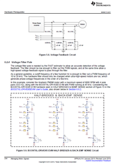
- What is the purpose of filtering in the voltage feedback circuit, when use the InstaSPIN library? Is it to eliminate the effect of the PWM carrier frequency or is there any special purpose?
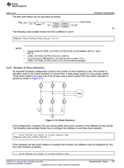
- How can I calculate the optimal LPF cutoff frequency?
I want drive 12-pole motor at a maximum speed of 28.6krpm, and the carrier frequency of the PWM is 28.6kHz. Since I want to pass a frequency component of under 2.86kHz, should I set the cutoff frequency to be roughly 3kHz? - I don't understand the meaning of the NOTE in the document above. What exactly does that mean?


