

Hardware Components
- TI LaunchPad MSP-EXP430F5529LP MSP430™ MCU LaunchPad™ development kit
- Texas Instruments MSP430 Microcontroller
- TI 430BOOST-CC110L Sub-1 GHz RF BoosterPack™ plug-in module
- TI BOOSTXL-EDUMKII Educational BoosterPack plug-in module MK II
- SparkFun RedBot Kit
- TI Battery BoosterPack plug-in module (x 2)
- SeeedStudio Grove Base BoosterPack plug-in module
- SeeedStudio Grove Starter Kit for LaunchPad kit
Software Apps & Online Services
- TI LaunchPad Kit Energia
- TI CCS Cloud
- TI Code Composer Studio™ integrated development environment (IDE)
STEP 1: Select Racerbot Chassis
When selecting a chassis that will be attractive for stocking a class with robotics we need to consider effectiveness and affordability.
Magician Chassis

This classic two wheel, dual level chassis is assembled using screws and standoffs (screwdriver included), and many options for mounting hardware to the platform. This is a solid chassis for classroom robotics. While Sparkfun no longer carries this chassis, it is available through other online retailers for $20-$30.
STEP 2: Select Motor Driver
Because we can't drive the motor(s) directly from a microcontroller (they draw far too much current), we'll need some type of motor controller/driver. This is a device that takes the low power signals from the microcontroller and turns them into high power signals that can be used to drive the motors. They also typically provide some protection circuitry so we don't destroy things if we make a mistake.
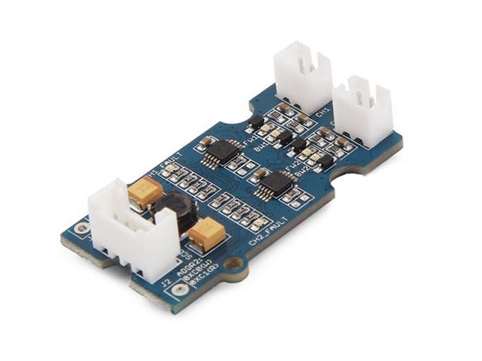
A preferred motor control IC for small robots like this is the TI DRV8830. Each DRV8830 can drive one motor at up to 6.8V and 1A. The real beauty of this device is that it is controlled by I2C. So instead of needing 4 PWM pins to drive a motor you only need a single I2C bus to control both speed and direction. This also makes it extremely easy to add additional motor controllers as they can all reside on the same I2C bus.
For this workshop we recommend using the Mini I2C motor driver from Seeed Studio. This board includes a Grove connector, two DRV8830's (i.e. drives two motors), and includes LEDs to show the direction each of the motors is going.
STEP 3: Build Robot Chassis
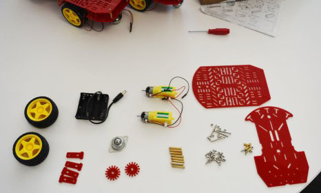
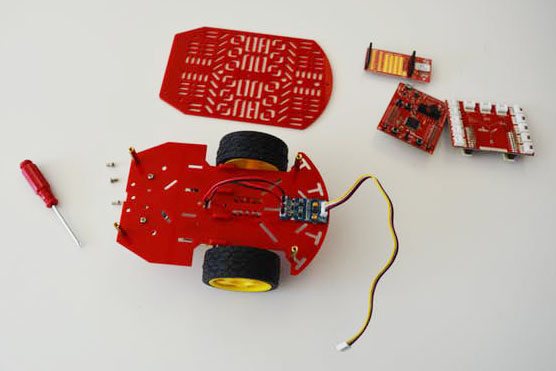
Disassembled parts out of the kit.

Attach the motor mount pieces to the main chassis plane.
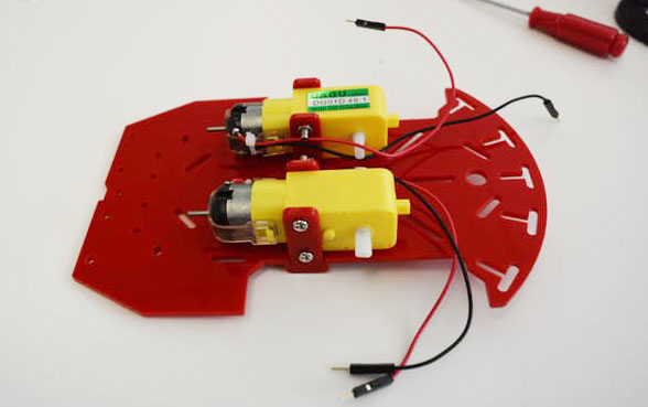
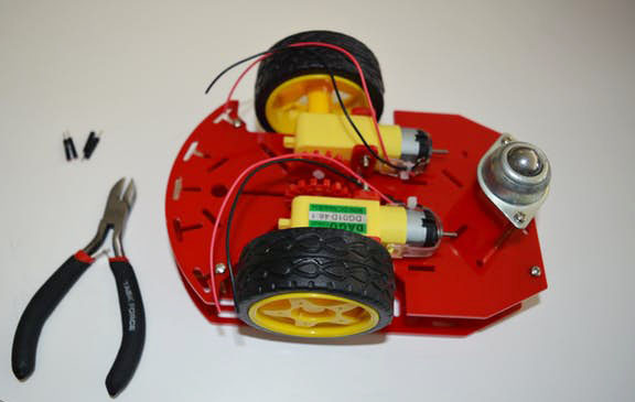
Screw in the motors making sure the shaft is aligned with the wheel bay using the long screws.
Note that the wire orientation can affect your software. You will either have black wires facing up or red wires facing up. This will change which way is forward and reverse. You can add the red gears to the interior shaft if you would like – but these are only cosmetic.

Attach the bearing standoffs (long) facing up with the included short screws.

Attach the bearing to the standoffs with the included short screws.
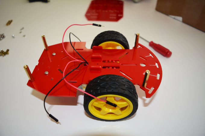
Attach the wheels, and thread the motor wires through the center hole.
Attach the standoffs (long) to the 4 edges of the chassis using the included short screws.
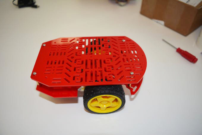
Screw together the top chassis plane using the included short screws.
The next step is optional. In order to plug into the Grove I2C Mini Motor Driver we need female connectors. The motors ship with male leads. You can either snip and replace the leads or find a way to adapt the motor driver for male leads.
Snip the ends of the wires and replace with female leads. Use wirestrippers to expose the copper leads and then attach the female connectors.
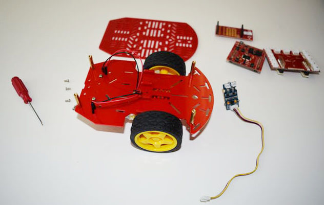
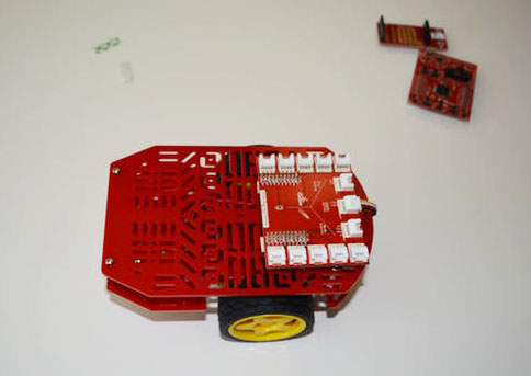
Attach the motor driver to the bottom layer of the chassis using double sided tape to save time.

Connect the female motor leads to the Grove Mini Motor Driver connectors.
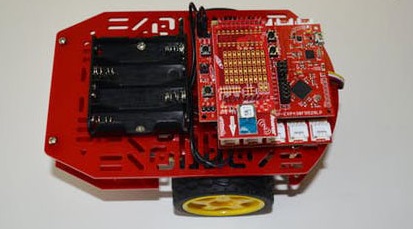
Get your MSP430 LaunchPad kit, CC110L BoosterPack plug-in and Grove Base BoosterPack plug-in ready.
Replace the top of the chassis and use double sided tape to mount the electronics. You can mount the hardware wherever you’d like, but the “front” will give room for the battery pack later.

Add the MSP430 LaunchPad kit to the top of the Grove Base BoosterPack plug-in.
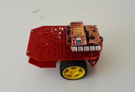
Add the CC110L BoosterPack plug-in to finish the stack. Be sure the pins are all aligned correctly.
Note the 4x AA battery pack ships with a barrel connector which isn't supported on the LaunchPad kit. You can either modify the wire or use another type of power source such as a battery BoosterPack plug-in.

Lastly stick on the battery pack. You likely need to modify the wire connection to female leads. Now you have a solid and modular robotic vehicle prototype.
STEP 4: Build Remote Controller
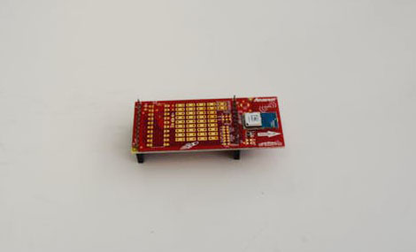
Take out your CC110L BoosterPack plug-in and make sure it is oriented with the blue module on the right side.
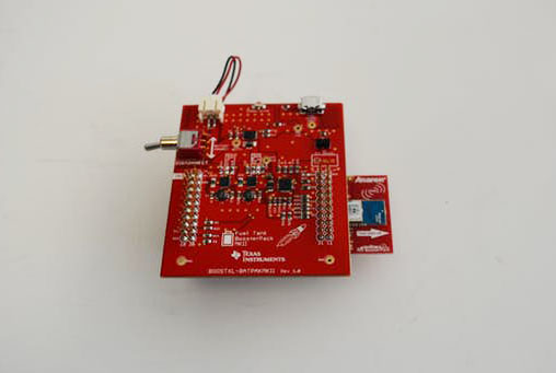
Take out your Battery Fueltank BoosterPack plug-in. Place the Battery BoosterPack plug-in on top of the CC110L BoosterPack plug-in and align the connectors.
Take out your MSP430 LaunchPad kit and place it on top of the stack, aligning the connectors.
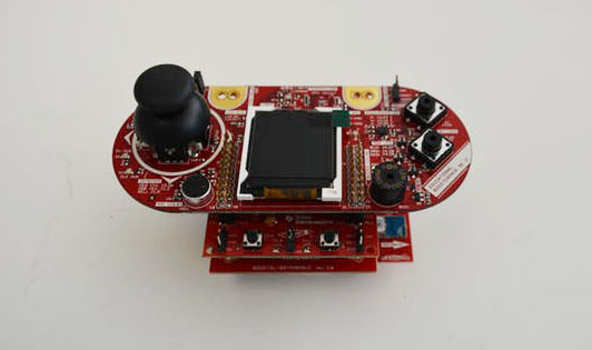
Finally, stack the Educational BoosterPack plug-in MKII on top. Now you have a functional remote controller.
STEP 5: Program Robot
Open up Energia and copy the code into a blank sketch. You can save it as MSP430Racerbot.ino.
Add a new tab for SparkFunMiniMoto.h.
Add a new tab for SparkFunMiniMoto.cpp
STEP 7: Program the controller
Open up Energia and copy the code into a blank sketch. You can save it as MSP430Racerbot.ino.
Open a new sketch in Energia and save it as RacerbotWirelessController.ino.
Conclusion
This is a very complex system but done relatively easily thanks to the modular hardware of the TI LaunchPad and intuitive software of Energia. Additionally you can add more sensors to the Racerbot to add features and capabilities that can teach important mechatronics concepts.
Have fun trying out your new racerbot!
