NOTE: No birds were actually injured during the writing of this post
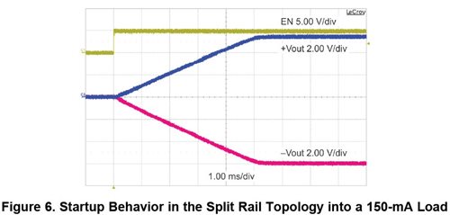
Consider the design challenge: you have a somewhat regulated input voltage (or perhaps a battery) and you need both positive and negative output voltages to bias your amplifier circuitry. In addition to being low noise, the output voltages should be symmetrical and start and stop with each other. Your ideal startup scenario is this:
Looks perfect doesn't it? Now, try implementing that with two different power supplies—one for your positive voltage and a different one for the negative voltage. Chances are that those two different regulators won’t start up in the same way or give as pretty a picture. They might have very different soft start times or simply different start up routines. But the bottom line is that they won’t match each other on startup. That may not be desired by your amplifier.
A ‘split-rail’ converter, shown at the top, is a solution to this dilemma. Using a single IC, the two output rails are produced. And they track each other nicely in the typical amplifier application which has a relatively balanced load. So, now you have the tracking of both voltages that you want, while saving cost by using just one IC!
While almost any wide input voltage IC can be used in the split-rail topology, the TPS62150 used here uses the low noise DCS-Control topology. With this, you may not even need those LDOs to clean up the output voltage—saving some precious power.
How is the split-rail architecture useful in your designs?
Additional Resources:
- Download a data sheet of the TPS62150.
- Find out about DCS-Control.
- Check out TI's low-power DC/DC converters with DCS-Control capability.


